|
|
|
|
|
|
|
Do you want to be a better CNC'er in 37 Seconds? Get Better Tool Life, Surface Finish, and Material Removal Rates Fast. It's that easy. You can install and get results now. |
 |
Circular Arcs With G02 and G03: Part 2 |
All the sneaky stuff you'll want to know about arcs after you've gotten the basics down!
Variations in Arc Syntax for Different G-Code Dialects and Modes
When IJK Are Not Incremental and What About Having Both IJK And R? Plus, Other Modal Shenanigans and Arc Variations
This is another one of those places where lots of obscure things happen and you need to know what your controller will do without assuming anything. In general, the rule is supposed to be that if you have both IJK and R in the same block, R takes precedence and IJK is ignored. But there are controllers that don't work exactly that way, so be sure you know what's going on.
G-Wizard Editor let's you specify several parameters in its Post that determine how arcs work. Here is a screen shot of the setup options:
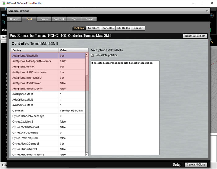
Arc Options for G-Code Simulation
Let's go over these options:
- Incremental vs Absolute IJK: We've discussed IJK as offering coordinates relative to the starting point for the center. Add the I to X, J to Y, and K to Z of the starting point and you get the center. Many controls also have the option for IJK to be the absolute coordinates of the center.
- Modal IJK Centers: When IJK are absolute center coordinates, some controllers will remember the last center defined, hence IJK is modal in that case. When using a control set up like this, you can just keep issuing XYZ commands for arcs without having to define a new center each time. It's not clear you'll save much though--how often do you want to do a bunch of arcs with the same center?
- Modal R Centers: Another variation on the modal center idea is to allow the radius defined by "R" to be modal. Whatever the last R used was, the controller remembers and uses that value again if no R is given. This seems more useful than modal IJK. For example, a pocket might have arcs for the corners that are all the same radius.
- Give R Precedence: As mentioned, most controllers will use "R" when both "R" and "IJK" are given in the same block. But this option allows you to change that precedence to IJK if your controller works that way instead.
- Helical Interp.: This option governs whether your controller allows helical interpolation.
The Most Common Problem Configuring a CAM Post or CNC Simulator: Absolute vs Relative IJK
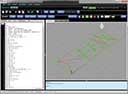
We've all had the experience of looking at a backplot (or worse, seeing it in the actual tool motion which is pretty scary) and seeing the giant almost complete circles and no sign of the familiar part motions we expected to see. Here is a typical example:
Engrave file with bad Post settings for Arcs...
If you see that sort of thing, the first thing to check is absolute versus relative IJK for arcs. The setting has to match between what the CAM produces and what the controller or simulator expects.
Fractions of a Circle, Quadrants, and Controllers
The first thing about an arc is it isn't possible to specify more than a 360 degree arc. There are some exceptions to this on some controllers for Helical Interpolation (see below), just because it can be useful for helixes. When a full circle is desired, set the start and end points equal to one another:
G01 X3.25 Y2.0
G02 X3.25 Y2.0 I-1.25 J0
Interestingly, you can't specify a full circle with the "R" notation. This is because there are an infinite number of circles that start and end at the same point of a particular radius, so the controller has no idea what the correct circle might be.
There is more funny business still with "R" and larger arcs. For example, an arc may still be of a particular radius and clockwise (or counter-clockwise direction), but the center is ambiguous if you travel more than 90 degrees. For example:
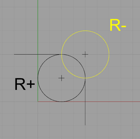
If R is negative, it takes the longer path (in yellow). Positive gets the shorter path.
Given the two choices shown, the controller chooses the path based on the sign of the radius. Negative forces the longer arc, positive the shorter. The negative sign forces the controller to seek a viable arc of more than 180 degrees.
Some controllers are touchier still and will not program an arc that crosses a quadrant line. Hence, the largest angle an arc can follow is 90 degrees, and that angle must not cross 0, 90, 180, or 270 degrees. For angles of 90 degrees that cross a quadrant line, they must be broken into two pieces, with the join between the pieces being right on the quadrant line.
Full Circles With No XYZ
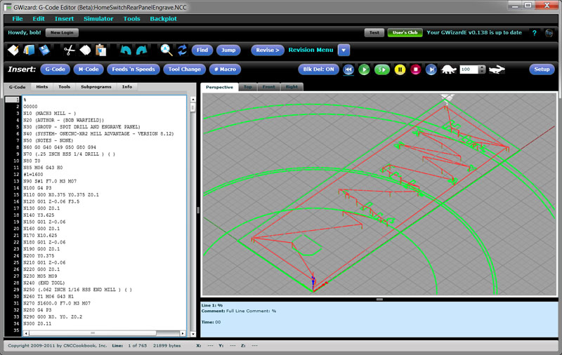
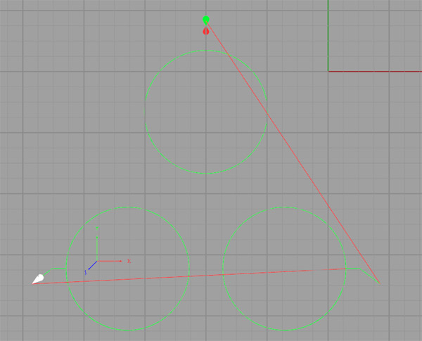
Full circles come about when the start and endpoints are identical and the center is specified via IJK (remember, R leads to an infinite number of circles). Given that you want the start and endpoint to be the same, you may not need to bother even specifying the end point with XYZ. Some controllers may require it, but most do not. Here's a simple g-code program that produces 3 circles in this way:
N45 G0 X-2. Y.75
N46 G1 Z-.5 F10.
N47 Y.5 F30. S2000
N48 G2 J-1.1
N49 G1 Y.75
N50 Z.2
N51 G0 X.75 Y-3.4
N52 G1 Z-.5 F10.
N53 X.5 F30.
N54 G2 I-1.1
N55 X.75
N56 Z.2
N57 G0 X-4.75 Y-3.4
N58 G1 Z-.5 F10.
N59 X-4.5 F30.
N60 G2 I1.1
N61 G1 X-4.75
N62 Z.2
And here's what the backplot looks like:
Tip to Make Arc Programming Simpler: Start With Segments
When I'm laying out a toolpath, I prefer to leave the arcs until last. In place of each arc, I simply put a line segment whose endpoints correspond to the arc's endpoints. This makes it easy to get the rough sketch of the toolpath together quickly, and it often seems to make it easier to then go back and convert the lines to arcs once the basic structure is already in place.
Helical Interpolation
A helix is an arc that continuously moves in a third dimension, like a screw thread. With helical interpolation, we specify such an arc with G02/G03 in order to move the cutter along a helix. This can be done for thread milling, interpolating a hole, or a variety of other purposes. Here is a backplot from a 1/4" NPT thread mill program:
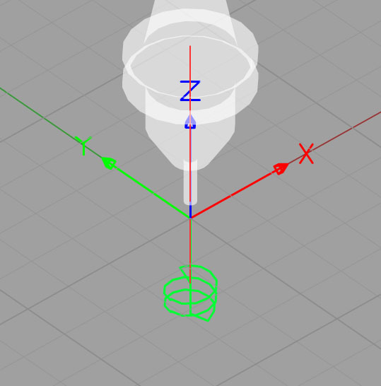
Helix for thread milling...
Here is a sample of the code from the thread milling program:
G01 G91 Z-0.6533 F100.
G01 G42 D08 X0.0235 Y-0.0939 F10.
G03 X0.0939 Y0.0939 Z0.0179 R0.0939
G03 X-0.1179 Y0.1179 Z0.0179 R0.1179
G03 X-0.1185 Y-0.1185 Z0.0179 R0.1185
G03 X0.1191 Y-0.1191 Z0.0179 R0.1191 F16.
G03 X0.1196 Y0.1196 Z0.0179 R0.1196
G03 X-0.1202 Y0.1202 Z0.0179 R0.1202 F26.
G03 X-0.1207 Y-0.1207 Z0.0179 R0.1207
G03 X0.1213 Y-0.1213 Z0.0179 R0.1213
G03 X0.1218 Y0.1218 Z0.0179 R0.1218
G03 X-0.0975 Y0.0975 Z0.0179 R0.0975
This is "R" (radius) format for the arcs, and note there is a Z coordinate to specify a depth change for the end point of each arc. This code uses relative motion (G91), so each "Z0.0179" moves the cutter 0.0179" deeper.
G-Wizard Editor provides some really useful information to help out with understanding helical interpolation. Here is the Hint from the third line (first arc move):
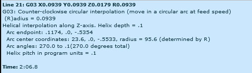
Note the thread pitch here is calculated as 0.1"
GWE will measure and tell you the helix pitch, which in this case is 0.100". That can be useful for identifying what sort of thread is being milled. We can also see that this particular arc runs from 270 degrees to a scosh more than zero (0.1 degrees).
We'll revisit thread milling in much more detail in a later chapter devoted entirely to the subject. For now, we just wanted you to be familiar with the idea that you can make helixes as well as flat two dimensional arcs.
Making Toolpaths Your Machine Will Be Happier With
Whenever the cutter changes direction, it adds a certain amount of stress. The cutter will bite into the material either more or less than it had been, depending on whether the directions changes towards the workpiece (or uncut material) or away from it. Your machine will be much happier if you program an arc rather than an abrupt straightline change of direction. Even an arc with a very small radius will allow the controller to avoid changing direction instantly, which can leave a mark in the finish in the best case and cause chatter or other problems in the worst case. For slight changes of direction, it may not be worth it. But the more abrupt the change, with 90 degrees being very abrupt, the greater the likelihood you should use an arc to ease through the turn.
Arcs are also a useful way to enter the cut, rather than having the cutter barge straight in. For information on entering the cut with an arc, see the toolpath page from the Milling Feeds and Speeds Course.
Exercises
1. Dig out your CNC controller manual and go through the arc settings to set up GWE to match your control's way of operating.
2. Do some etch-a-sketch experimentation with GWE. Create some toolpaths that include arcs until you're comfortable creating them.
3.
Try the Free Trial Version of G-Wizard G-Code Editor...
![]()
No credit card required--just your name and email.
Next Article: Running the GWE G-Code Simulator
|
Do you want to be a better CNC'er in 37 Seconds? Get Better Tool Life, Surface Finish, and Material Removal Rates Fast. It's that easy. You can install and get results now.

|
||||||||||||||||||
| ||||||||||||||||||