Beginner's Guide: Make G-Code and CNC Coordinates Easy
CNCCookbook's G-Code Tutorial
Quickly learn how CNC coordinate systems work for CNC mills and lathes from 2 to 5-axis. It's so much more fun to know what's going on, and mastering coordinates is one of the first steps. Plus, it's just not that hard--we'll show you how right now.
Does CNC use a Right or Left Handed Coordinate System?
Hold up your right hand with the index finger extended and the thumb up, like you're simulating a gun. Now extend your second finger at right angles to the index finger. Those three fingers are now pointing in the directions of positive X (second finger), Y (index finger) and Z (thumb). In other words, the Z coordinate will get smaller as your spindle moves down towards the table of a mill. Now here is the tricky part:
Even if the table moves instead of the spindle, the handedness is based on the assumption it is the spindle moving!
What that means is that for motions of the table, we reverse directions. Hence even though the diagram shows what looks like a left-handed system, if we consider how to get the same motion if the spindle moved instead of the table, we'd see it is really right handed.That's why we say CNC uses a Right Handed Coordinate System, and the whole hand thing is just an easy way of remembering. Even though most machines are right handed, it is not a requirement, and you need to check out how your machine is actually set up.
This whole handedness thing is just a way to remind yourself which way the coordinates go. It's not a big deal otherwise and you'll get used to what your machine uses pretty fast.
Each machine will have its own specific axis orientation which you should become familiar with. Here are some common types:
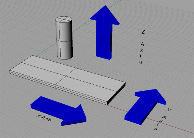
Mill Axes for a Typical Vertical Machining Center. Note: arrows show table motion in positive g-code direction. Handedness is spindle motion and reversed!
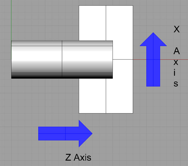
Lathe Axes for a Typical 2-Axis Lathe...
The cylinders in each drawing represent the spindle of the machine. Be sure to have a look at exactly how the axes are laid out on your machine. For example, horizontal mills are turned around considerably from the drawing I've shown. Lathes can get a lot more complicated than the simple 2-axis version I've shown.
4-Axis, 5-Axis, and More
Much more complex configurations are possible when you have more axes. For example, here is a 5-axis setup:
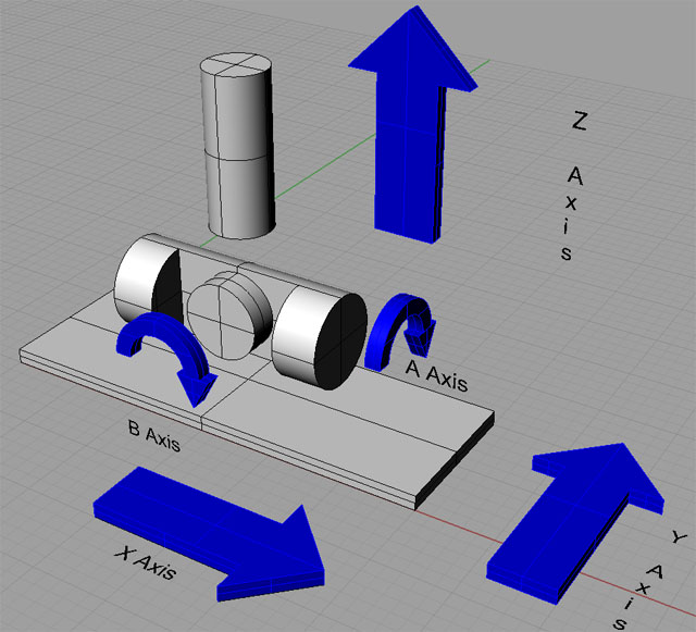
5-Axis Mill With Trunion Table...
Note that we have added two rotational axes to the basic mill diagram to provide an A-Axis and a B-Axis. In general, A, B, and C are rotational axes that rotate around axes formed by the X, Y, and Z respectively.
Expressing Coordinates in G-Code
Now that we know what the coordinate systems are, how do we express coordinates in G-Code?
It's pretty simple: just take the axis letter and add the value. Spaces between the letter and its value are optional.
For example, a position that is 1 inch from 0 along X, 2 inches along Y, and 3 inches along Z is written as:
X1Y2Z3
You get used to reading them all run together like that quickly, but you can format them with spaces to make them more readable:
X1 Y2 Z3
or
X 1 Y 2 Z 3
Again, you get used to keeping the letters with the numbers, so I wouldn't add more spaces than just between the axes:
X1 Y2 Z3
That's actually the easiest to read once you get used to it.
What About Units?
The example I just gave used inches, but in actuality the controller can be set to use either metric or Imperial. It's up to you to know which default the system comes up in and to change the units as needed. Try not to change units in the middle of a program, do so at the very beginning and then stay with the same units. It's too confusing otherwise. The G-Codes to change units only affect how the machine interprets the numbers. They don't change your program. We'll talk more about changing units in a future article, but for now, just be aware.
For rotational axes (which you'll only be using on a 4 or 5 axis machine), we don't use dimensions for the units, we use angles, typically in degrees. Rotating the 4th axis to the 90 degree position might be done as A90, for example.
Relative Versus Absolute Coordinates
Sometimes, it is very convenient to refer to Relative instead of Absolute coordinates. Let's assume the tool tip on my mill is at X0 Y0 Z0 and I want to move it to X1 Y2 Z3 (I dropped the commas, which are not used in G-Code, because I'm just trying to get you used to the switch from how you learned coordinates in school, e.g. (0, 0, 0), to how it's done in G-Code X0 Y0 Z0). I can make the move absolute or relative and it doesn't matter. "X1 Y2 Z3" does the trick since in either case we started from X0 Y0 Z0.
But, suppose your cutter is positioned at some point and you need to cut a 1" square with the corner aligned to that point. Perhaps you've used your edgefinder to locate the cutter precisely on some feature of the part. This is easily done with relative moves:
X1
Y1
X-1
Y-1
In essence, move 1" right, 1" up in Y, 1" left, and then 1" down in Y. Now we have a 1" square whose lower left corner is the initial point.
There are lots of cases where relative moves are handy so the ability to switch back and forth comes up a lot. We'll show you how to make that switch when we talk about how to move with G-Code, but for now, just be aware that there are both Relative and Absolute Coordinates.
Sometimes, we refer to relative coordinates with special axis letters. For example, IJK may be relative XYZ when defining arc centers. On some controllers, UVW may be used alongside XYZ to refer to relative coordinates without needing to change back and forth between relative and absolute modes. In other words, XYZ is used always as absolute and UVW is always relative.
For now, it is enough to be aware that relative coordinates exist. A little later, we have an entire chapter just on the subject of relative versus absolute coordinates.
Offsets
The last Coordinate System concept I want to cover is that of Offsets. Offsets are another fancy way to think about relative motions. Let's suppose you want to machine 2 identical parts. Each is held in a vise on your table at the same time. How do you make one program that can do both parts without having to change the program for the position of each part?
The answer is that we use a Work Offset. More detail on those later, but for now, imagine that Work Offsets let us position the X0 Y0 Z0 origin in more than one place. We can put one on the first vise and another on the second vise. Now just by changing the work offset the same program can work to make the part on either vise.
There are lots of different kinds of offsets in CNC, and the skilled CNC operator/machinist finds that offsets are an extremely handy way to nudge the behavior of a G-Code Program without having to change that program. Most CNC controllers have an offsets screen where you do that. I mention this because any time you get a chance to learn about offsets, take the time to do so. They're digital power tools for the CNC machinist and are very handy. We'll cover them in greater detail later.
Planes
It's convenient to refer to planes for various purposes. A plane is a flat 2 dimensional space defined by two axes. For example, the default plane on most mills is XY. If you draw an arc without specifying a change in the plane, it will be drawn on the XY plane. There is a plane for each combination of the linear axes XYZ:
The G17, G18, and G19 G-Codes select which plane is active. More on G17-G19 when we talk more about arcs.
Conclusion
You've now got the basics:
- You know how to visualize the coordinate systems relative to your machine using the left handed rule.
- You know how to express coordinates in G-Code.
- You know what units are used to measure the coordiantes.
- You know there is the possibility of both relative and absolute coordinates.
- You know that offsets let you shift the coordinate system around for various handy purposes.
- You know about planes.
We'll shortly introduce the notion of MDI, which is a simple way to use G-Code as though you are still a manual machinist. It's a good introduction to the basics of moving your CNC's axes. But first, we need to get you set up on G-Wizard Editor so you'll have a CNC Simulator to use for practice during these tutorial lessons.
Exercises
1. Form the left-handed and right-handed coordinate systems with your own hands and visualize which way the axes run on your machine. Which direction is the positive (increasing positive coordinates) for each axis? Which direction do increasingly positive coordinates in the g-code move the table and spindle?
2. Get out the manual for your machine and find the diagram that shows how its coordinate system works. Make sure to leave the manual handy, whether it is paper or online. We'll refer back to it a number of times as we go through the various exercises.
3. Bring up G-Wizard G-Code Editor. By default, you're in Mill Mode. There are views for Perspective, Top, Front, and Right. Download the sample engraving file from our download page. You want the file called HomeSwitchRearPanelEngrave. Start up GWE and do a File Open to load the downloaded file. Have a look at it in each view.
- Top is a view from the XY plane
- Front is a view from the XZ plane
- Right is a view from the YZ plane
Try the Free Trial Version of G-Wizard G-Code Editor...

No credit card required--just your name and email.
Next Article:G-Code Dialects, Post Processors, and Setting Up GWE