|
|
|
|
|
|
|
Do you want to be a better CNC'er in 37 Seconds? Get Better Tool Life, Surface Finish, and Material Removal Rates Fast. It's that easy. You can install and get results now. |
July Through September 2006 CNC Blog Archive
9/28/06
Eliminating Backlash
For the benefit of those trying to eliminate backlash, I spent the evening writing a couple of Cookbook recipes that gather up as many ideas and thoughts as I could, based on my travels through the Internet.
Eliminating Backlash Part 1: The Basics. This is a basic treatise on ballscrews and using angular contact bearings to mount them.
Eliminating Backlash Part 2: Refinements. This assumes you've got your ballscrews installed and you are still not happy, which is the case here. There are some things I've run across that have not been mentioned often, and I hope that putting it all together in one place will be helpful as well.
9/24/06
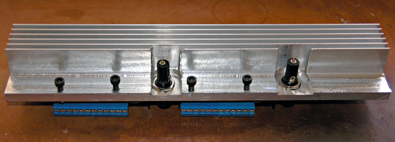
Gecko Drive Mounting Bracket for CNC Lathe
After looking over what others had done to mount their Gecko drives, I decided to use some heatsink extrusion to make a bracket. I mounted the fuses in the bracket right next to the appropriate drive:
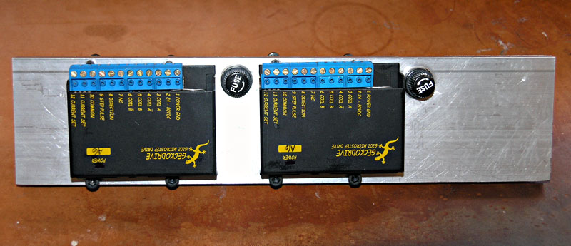
I need to put a label next to each drive so I can tell which axis is which. One more thing done building the driver electronics enclosure. The next step is to build a sub-chassis that will carry the relays and other auxilliary components needed to control the spindle and coolant.
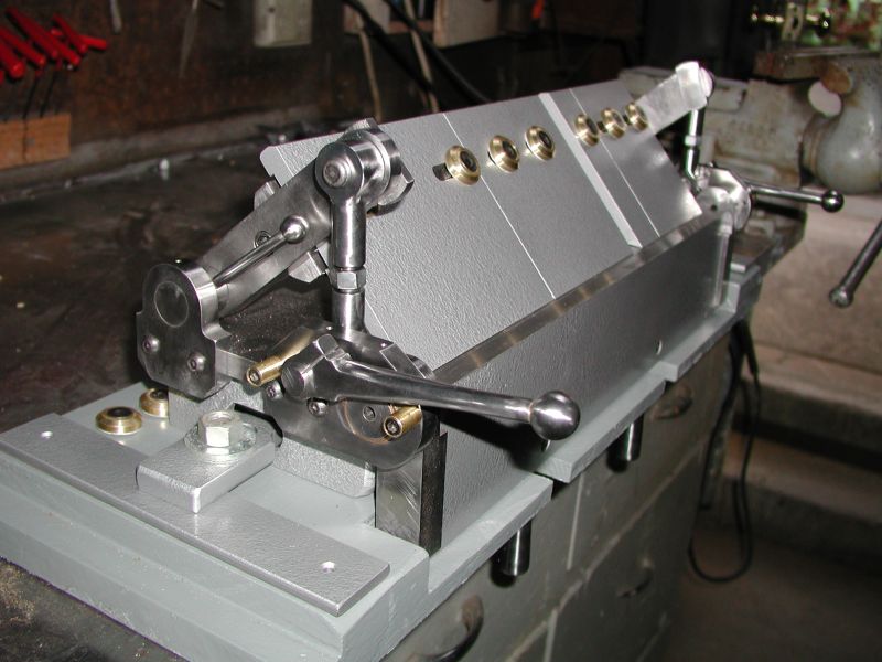
Tapping Arms
I had occassion to drill and tap some holes on my CNC Lathe project (making a heatsink/mounting bracket for the Gecko Drives), and got to thinking about Tapping Arms:
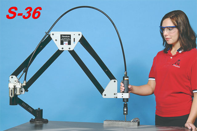
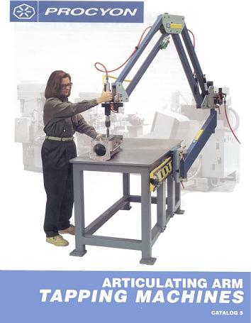
These gadgets are designed for production shops so that someone can rapidly tap a whole bunch of holes. They look extremely handy and easy to use, and I've heard lots of good about them on Practical Machinist (the owner of the site seems to have invented the darned things!). I sure could have used one for my project! The subject comes up on Practical Machinist usually because someone can't do rigid tapping in their CNC. Someone else usually suggests they buy a tapping arm rather than a new CNC. This is relevant to amateurs because Mach 3 doesn't support rigid tapping at the moment. The only bad news is that they seem to cost $1200 to $5000 and up. Wow!
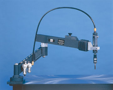
The interesting question is how hard would it be to make one of these gizmos? The arm itself is very simple. In a pinch, you could probably use a monitor arm designed for a PC, assuming you were willing to accept a little lower capacity and strength. What about the motor? I'm thinking an import butterfly impact wrench or something similar is about perfect. Failing that, it seems like you could adapt a Tapmatic or other tapping head to an air or electric motor. Whatever motor is used needs to be reversible. What I like about these things is they look like they would make tapping a snap and they also stay out of the way. I could imagine attaching one to the corner of the welding table and forgetting about it. Seems like a perfect small workshop project!
Nice Rail Design for Plasma and Router Tables
All in all, looks like a pretty decent railing system that would be easy to build.
9/22/06
Big Doings for the Site
After much head scratching and soul searching, I've decided to decouple the look and feel of the machine tool pages from the rest of TheWarfields.com. You have in your hands the result of that effort. I'm hoping the navigation makes a little more sense, the design is a little cleaner and crisper, but most of all, that it just makes these pages more useful and more fun. Before launching into this move, I spend quite a lot of time poking around the Internet to see what I liked in various sites. I'm pretty happy with the overall result.
9/19/06
Cool 5-axis Milling Head
DS Technologie Z3 5-Axis Head...
It uses 3 sets of linear rails in a triangular configuration with pivots. I wonder if Mach 3 can handle the kinematic formulas for this kind of thing? Woo Hoo!
I like it because it looks easier to build than the typical 2-rotary-axis machines.
9/17/06
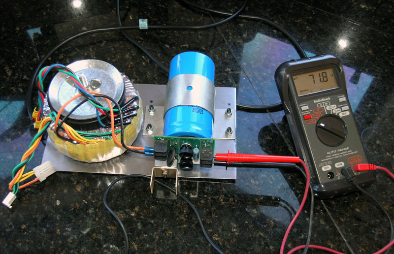
Finished the DC Power Supply for my CNC Lathe project this weekend!
Options for entry level CNC
I was recently perusing a thread on Practical Machinist, and as I watched the feathers fly, what first seemed like total disagreement and conflicting evidence gradually coalesced into a stratified view of the options. It is basically a trade off between performance versus dollars and personal skill. You can offset dollars with a lot of personal skill to modify a machine and improve its performance, or you can use dollars to buy a higher performance machine. The pecking order for dollars/skill looks like this:
|
Most Skill
/ Least Dollars |
|
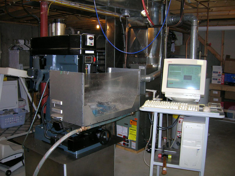
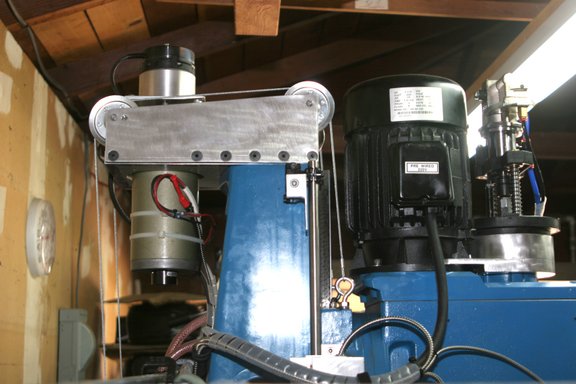
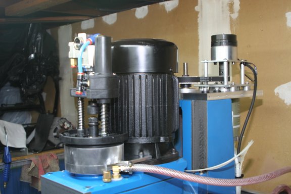
- Do your own conversion. This is the path I am following on my CNC Lathe, albeit slowly. One thread contributor, Dirt Rider, proved the lowest end can succeed brilliantly if you have the right skills. He did this even starting with a round column mill, thought to be the lowliest of lows by many. I'm not sure the Haas guys can show nicer parts, but they probably make more of them faster. With that said, this would clearly require a lot of time and personal skill to duplicate.
Simple round column mill with flood coolant enclosure...
Gives spectacular results! |
|
- Modify or retrofit a machine. This is
very close in cost to "buy a kit" and also in the demands it places
on your skills. One of the best examples here is our very own "Anvil".
Track down his threads about his Tree 325. It's an older CNC knee
mill, and he produces spectacular results with it: www.anvilbikes.com.
There is a lot to be said for finding an older CNC mill whose controller
is dead, and refitting it with a PC/Mach 3 controller. If you get
lucky, the spindle, ways, ballscrews, motors, and power supply will
all be good and you wind up with a fantastic mill for a good price.
I've been watching the Tree 325 market myself, and it looks to be
about a $3500 machine. One could also easily refit a Tormach with
servos. Go find the right NEMA form factor servos, replace the stepper
Geckos (2xx series) with servo Geckos (3xx series), and you are
done. I would also upgrade from Mach 2 to Mach 3. This would be
a trivial upgrade and should allow you to dial in much faster performance.
I am surprised nobody has tried it yet. |
|
- Buy a kit. Industrial Hobbies is probably
the best example, and I bought their kit to eventually install on
my IH Mill (gotta finish the lathe
first!). A couple of things to note. They just revised their basic
mill to use ground ways--no more lapping, which one thread fellow
was on about. It also uses servos, which I
agree are higher performance. There are some movies up no on
their site so you can see it in action. Take a look at "making a
small part". Compare that to the videos on the Tormach site and
you can see how much slower the Tormach is. Again, it may not matter
to your application, don't get overly hung up on it, but it is a
great demo of the servo vs stepper performance gap. |
|
- Buy a real VMC used, but working: Cheaper
than new, make sure you know how to evaluate one. |
|
- Buy a new low end VMC: This is the Rolls
Royce route, but if you have an immediate business opportunity making
parts in any volume, it may be your best option to getting your
business successful as quickly as possible. |
|
Least Skill
/ Most Dollars |
9/15/06
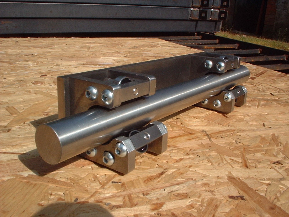
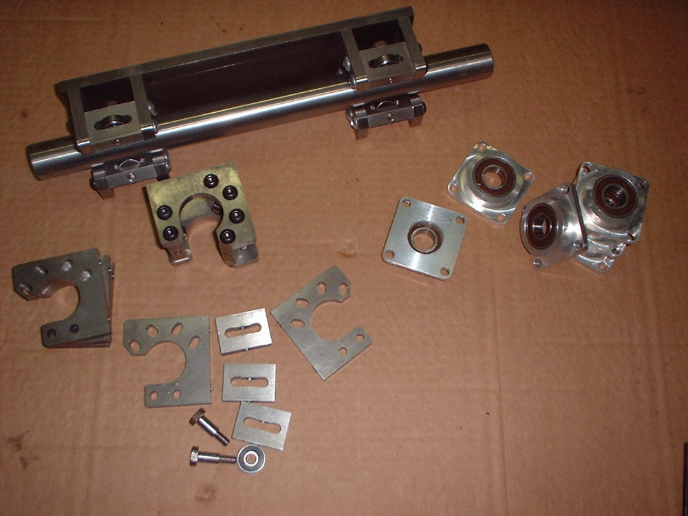
Precision Linear Rail Support With Moglice for Gantry Machines
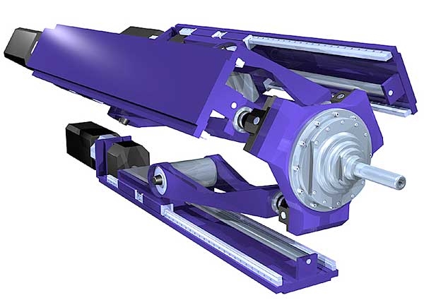
I've been doing a lot of pondering lately after reading an MIT PhD MechE's thesis on designing and building CNC machines. To find your own copy of this 200+ page tome, Google for "Principles of Rapid Machine Design." The fellow that wrote it is a Professor Bamberg, who injected a number of thought provoking ideas via his thesis into my consciousness as far as how to build machines that will be very accurate yet relatively inexpensive and straightforward to create for an advanced Home Shop Machinist. Once the juices got flowing, it resulted in the 5-Axis T&C grinder doodle below. I wanted to set down here another application, which I've been discussing with JerryFlyGuy and others over on the CNCZone, and that is how to mount linear rails on a fabricated (likely welded) substructure with precision.
The salient idea is to make the precision structure on which the rails are mounted separate from the fabricated (often welded, but could be bolted together) structure needed for support and rigidity. The magic interface between the two is a special epoxy used by machine builders called Moglice. Note that this method is also useful when attaching two parts of a machine together that require a precise orientation to one another, for instance, when getting a column square with the base of a mill, or perhaps even getting headstock of a lathe square with the bed.
In practice, one fabricates both pieces separately, and then bolts them together leaving the bolts loose enough so there is an approximately 1mm gap between the two. A system of setscrews (or leveling screws if you prefer) is used to achieve the precise alignment desired, and then Moglice is injected between the two. When it sets up, there will be a precision match between the two surfaces that retains the alignment achieved by the set screws. One can then remove the setscrews and torque down the final mounting screws against this precision surface, and all will be well.
This approach appeals to me greatly for a few reasons. First, it's blessed by an MIT PhD, and was used in a commercial high peformance 5-Axis CNC Grinder he collaborated on--gotta love that! Second, it takes the art of precision machine construction out of the realm of laser interferometers and hand scraping and moves it closer to adjusting a 4-jaw chuck on your lathe.
Now to be sure, one does need a precision surface to mount the linear rails to--you can't just bolt it to any old wavy piece of metal. However, that precision is straightforward to achieve with a surface grinding operation. Used surface grinders are cheap, Asian import new surface grinders are cheap, and shops with grinders one could farm the work out to are plentiful. Moreover, it is only the shoulder and the floor surface immediately under the linear rail that needs this treatment. It is concievable that with enough care, perhaps one could even achieve decent results in aluminum finished with a fly cutter and skip the surface grinding stage. It's largely a question of the accuracy you want the machine to achieve. I would think a tenth (0.0001") would be straightforward with surface grinding.
Let's see how this looks in plan form:
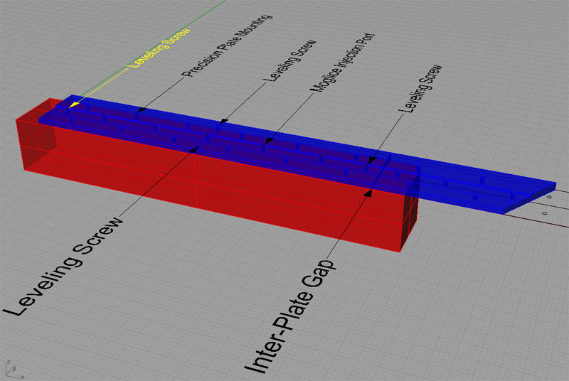
The precision plate (blue) sits atop the structural frame (red). Linear rail mounting holes not shown for clarity.
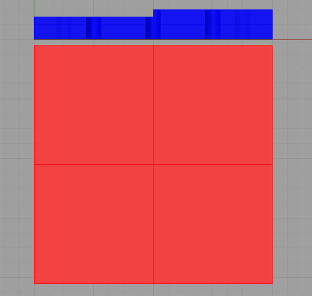
A precision ground shoulder in the precision plate locates the linear rail straight, level, and true...
In practice, one would use a bead of silicone cement to "o-ring" the Mogliced gap so all the Moglice stayed in place until it hardened. Getting the plates straight, level, and true should not be too challenging with a tenths indicator, straightedge, and machinist's level as your tools. All it takes is a little patience and skill with these normal tools of the trade. No finicky scraping that requires "touch" and years of experience to do well.
We apply a similar principle to mount the gantry and keep it true. The gantry uprights would have a flange at bottom accomodating the same mounting hole+set screw+Moglice port model shown here. Work step by step, use the leveling screws to get the gantry right where you want it, and inject the Moglice to lock that in.
It is a tremendous advantage that the structural framework can be built, seasoned, set up and leveled in the place it is inteded to be used all before the precision work really gets under way. I have on my list of researches to understand what is needed to season such a frame. I understand there are approaches based both on temperature and vibrational techniques. Some passage of time would also seem to be advantageous. I wouldn't go injecting Moglice the same day I'd finished welding up said frame, for example.
9/14/06
What's this then?
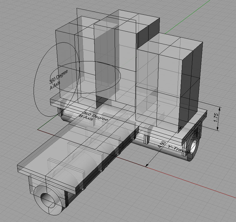
Sketch of a 5-Axis T&C Grinder Frame...
9/11/06
Tool Height Touchsetting/Presetting
Got interested in researching tool height touchsetting/presetting over the weekend and collected my notes on the new CNC Tips & Techniques page. Since I haven't yet got a machine converted, I'm not ready to put any of it into practice, but it was interesting reading.
Moglice and Sliding Bearings
Ran into a query about using Moglice to fill gaps between column and base when squaring the mill. Did a routine web search and discovered the patent application for Moglice is #4,329,238. Also came across a fabulous MIT lecture notes on sliding bearings (e.g. what we call "Ways"). It had some interesting information. Sliding bearings made with Moglice, may not require gibs, for example, because the fit is exact. Only the master need be accurately scraped, as the secondary bearing is cast in Moglice. This begs the question, if we have a precision straightedge of sufficient size, can we simply cast both sides of the bearing in Moglice, and do away with any scraping to build a precision machine tool? It would seem so.
One serious negative with Moglice is that it wears pretty quickly compared to cast iron. Provision must be made to protect the ways from contaminants.
9/3/06
It's alive! Finally got the PC for my CNC lathe project assembled
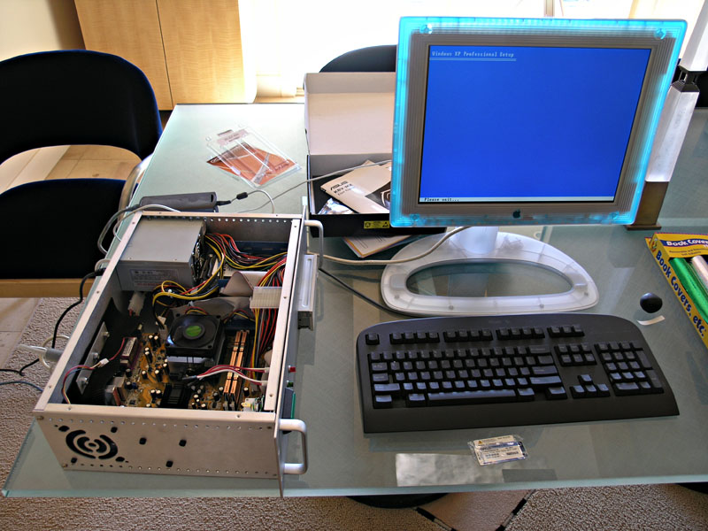
CNC Lathe PC having Windows XP installed...
It's a full on Athlon 64 system on a Micro-ATX motherboard. All the parts are brand new, and you can build a system like this for about $400 if you shop carefully, not including monitor, keyboard, or mouse.
Machine Table Covers
Clever idea: how about taking some sheet metal and some felt to create some table covers to make it easy to clean up when doing vise jobs?
Sheet metal table covers make cleanup easy!
Bridgeport CNC Conversion with Single Shot Oiling
Here is a great shot of a lot going on underneath a Bridgeport table:
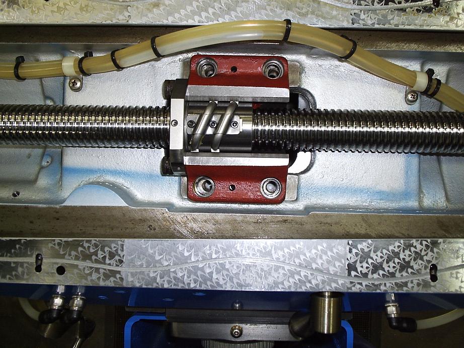
Nice single shot oiling tubing all tied off and clamped down, "groovy" oil passage on the freshly scraped way, and a brand new HiWin ballscrew. This is a very nice Bridgeport CNC conversion...
8/29/06
Ever hear of a "Maximator"? <Hint: Think Waterjets>
Apparently this type of liquid pump is exactly the sort of thing needed to drive a water jet cutter. Those beasts are way cool! If you're not familiar with them, water jets use super high pressure (20,000 - 60,000 psi and up) streams of water to cut with. Usually, the water carries a garnet abrasive. The results are very precise and smoothly polished, so it is an extremely efficient process. The fellow that runs Anvil Bikes says he reduced his machining costs 80% when he outsourced to a water jet shop to cut his workpieces so they required less machining to finish. That's quite a testimony! I've read in a number of places that rough cutting to within 0.1" can really save on the cost to machine a part. A water jet would be the ultimate. Flow International, one of the premier supplies of these high-dollar machines, claims their machines will cut to within 0.003". They do so without heating the part, with little lateral force, and with very little kerf, which is extremely helpful in many cases.
Just one problem with all this--water jets are expensive! They also generally take some pretty industrial support--they don't just plug into 110V. Some folks talk about building one from time to time, but I have yet to see anything come of it. But how about this idea: There is a waterjet rig built around an air powered maximator that could be attached to your CNC mill to do water jet cutting. How about attaching one to a plasma table to really open up some possibilities? We know the tables can be built cheaply. Brand new, the 30HP version of this thing from WardJet, the M-30, supposedly costs about $35K. Now we can see how to produce a 4' x 8' capacity waterjet for somewhere in the neighborhood of $50K. That's still a huge sum of money, but it's way less than a complete new machine.
It's interesting to watch the videos on the WardJet site. I found it particularly interesting that they use a bed of ball bearings to hold the workpiece so that the water jet doesn't eat up the bed too quickly. The hourly costs are also interesting--not exactly cheap gadgets to run, but the productivity is awesome, so there is a good return. To learn more, I did find a really good web site that's all about water jets.
It turns out I have a lot of things in my house that were cut with a waterjet by these guys:
Creative Cutting Service
65 Hangar Way
Watsonville, CA 95076-2476
( Monterey Bay Area )
phone: 831 728-5362 fax: 831 728-5364
email: lberk@redshift.com
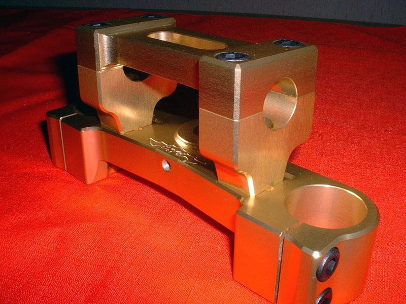
Thomas Powell has done some fantastic work on his IH Mill
His photo site details all of it, but there are some choice pieces I particularly covet:
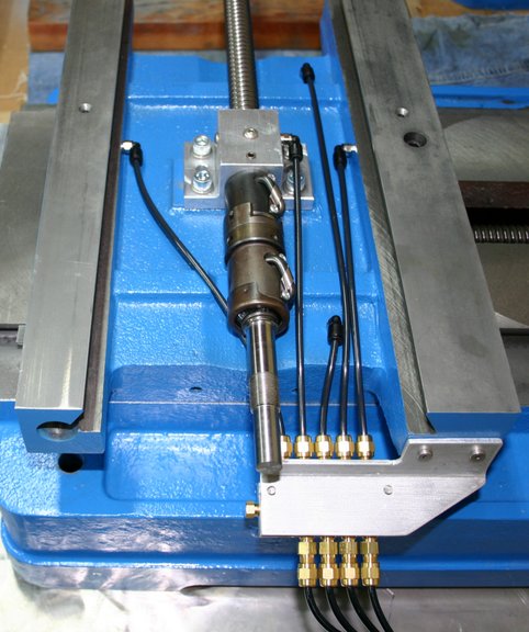
One shot oiler using Bijur manifold and orifices...
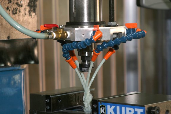
Spindle mounted flood coolant system and enclosure...
Z-Axis counterweight system using gas struts...
8/27/06
A Smithy mill-lathe converted for linear slides
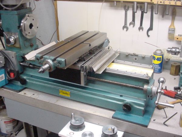
Smithy with linear slides...
The way covers are just rectangles of aluminum flashing with adhesive tape between each segment...
8/07/06
CNC Dictionary
I've been busy on a number of fronts, not the least of which has been the creation of a CNC Dictionary to help newcomers learn the newfangled terminology of this crazy technology as well as helping yours truly to stay organized in my own thinking and learning process. It's been great fun putting it together, but quite a lot of work.
Inexpensive DRO for the Mill
I've also been spending time down in the shop, getting two axes of my inexpensive DRO up and running:
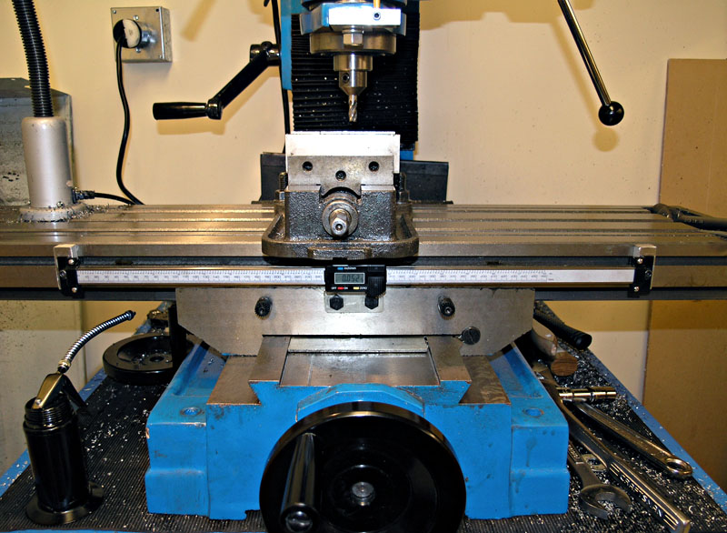
X-Axis DRO...
As I mention somewhere below, the scales are quite inexpensive, and they'll be very convenient to have in the interim before I convert to CNC. In fact, I plan to use them for a little while post CNC conversion to help me diagnose whether everything is working properly and to do some ballscrew error mapping to improve the accuracy of the machine.
Converting a Bridgeport Power Feed for the Industrial Hobbies Mill
Speaking of the interim, I also have a project underway to convert a power feed intended for Bridgeports for use on my IH machine. If you want one that's done and works well (according to all reports), by all means, purchase the model sold by Lathemaster. At $249, it's really not a bad deal, and after spinning the handwheels for a few projects, I've come to regard some kind of power feed as an eventual requirement. Here is the thing though. eBay seller "DiscountMachine" (aka Shars) will sell you a Bridgeport compatible power feed for $169, which is quite a good savings, and I have read some positive things about this unit over on Practical Machinist. I'm viewing the power feed in the same way I did the DRO--it's an expendable project that will be useful for a time until I convert to CNC. So, I decided to spring for one, thinking it would be easier to sell a Bridgie-compatible unit when I was finished with it, and that it couldn't be all that hard to adapt it to the IH Mill. Time will tell on the former, but it does not look too hard to adapt now that I have it in hand. I'm partway through making the shaft adapter (Bridgie has different dimensions, of course), and that adapter coupled with a simple plate to adapt the Bridgie bolt patter to the IH Mill and I should be in bidness as we used to say in Texas. I'll write the whole thing up when it's done and working.
And speaking of the CNC conversion for the mill, I got a note from Aaron today telling me they are shipping out my conversion kit. Yup, I broke down and ordered one last month. Considering how slowly the lathe conversion has gone, I thought it might speed things up a bit if I purchased a finished kit rather than engineering one myself. The mill is a more difficult project to get right anyway, and besides, Aaron had the darned things on sale. I ordered the mechanicals-only kit, and I'm thinking of using the Kelling Technology motors referred to below. These are 600 oz in motors at a great price, Mariss F. himself has blessed their usage in glowing terms, and I'd love to be able to compare and contrast a stepper system (my lathe) with a full closed loop servo system on the mill.
I Want to Build a Pan and Box Brake
I'll keep you posted on the mill progress, but frankly I do intend to build a few more projects using the mill manually before I dive into the conversion. For example, I need to build a pan and box brake to be able to finish the chassis work for my lathe retrofit. I love the design that appeared in "Projects in Metal", and have the book. They come out looking great:
I'm going to build a box brake just like this one...
I've got all the steel for it ordered and it is sitting in my garage. Just need to finish a few other projects (especially the mill power feed), DOH!
Centering Scope
I've mentioned below (7/7/06) my desire to own a Centering Scope. Being a very visual person, this just seems a great way to line things up, whether that be a 4-jaw lathe chuck job or something in the mill. After losing out on something like 6 scopes that all sold on eBay for over $200, I lucked out and snagged a Heco for $115. Go figure. I don't have it in hand yet, but I'll let you know how it works out when I get it.
Ongoing CNC Lathe Conversion
Lastly, I wanted to report that their continues to be some signs of glacial progress on the lathe conversion. As the duly appointed and solitary IT support person in our household, I was called to PC tinkering when the fan on my wife's PC went out. Having gotten my hands dirty fooling with a PC for the first time in a while, I thought it well if I got on with building the PC I want to use for the lathe. I've had the parts for some time, but needed to convert a 19" rack mount enclosure I got off eBay (what would I do without eBay?). It turns out to be quite a lot of trouble to convert a generic enclosure to be a PC. All sorts of little holes and openings have to be engineered in. Lots of crazy little things have to be scrounged up, like the little speaker to play your motherboard's beeps at startup. At this stage, I think I've got most of it in hand, and hope to try to assemble it soon. Once I've got a working PC, it'll be time to start on the drive electronics enclosure. That's one of the things I need the box brake for, to make a little bracket to hold the Geckos in an efficient way. One thing certainly does often lead to another, doesn't it?
Odds & Ends
How about mechanically compensating for leadscrew error? I came across an interesting article wherein Les Watts uses a mechanical system to correct leadscrew error to achieve 0.0005" maximum error over 60", an improvement of 12x over the out of box leadscrew spec. His issue was that he needed to drive a big router gantry with a leadscrew on either side and wanted them to match. One could be mapped in software to correct the error, but what to do about the other? He devised a mechanism that uses a mechanical cam to advance or retard the ballnut in order to correct errors. The really interesting question is not considered in the article, which is, how did he produce the cam used to correct the error? This same fellow writes in great detail of how he produced the very flat surfaces needed for the router using an interesting twist on scraping. Rather than use a scraper, he knocked the high spots down with a hand grinder, and used the standard bluing techniques to test. All in all, a very interesting and unorthodox set of techniques.
Tool & Cutter Grinders
I've been keeping my nose to the ground looking for ideas on a tool and cutter grinder. It's ridiculously easy to dull a cutter, and while they're reasonably cheap on eBay (say $10 for a nice US Made 1/2" endmill), it's even cheaper to sharpen them. Not to mention drill bits need constant sharpening, and custom cutters are easily made with the right grinder. I've looked a little bit at the Deckel's and their clones that come up on eBay, but they want an awful lot of money for one. Then there are a variety of cutter grinders that various HSM's have made over the years.
The Quorn is probably the most famous. It's a beautifully intricate little machine:
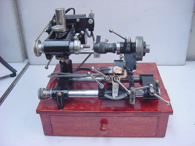
Quorn Cutter...
I have entertained the idea of CNC'ing up a Quorn out of bar stock after I get my machines converted, and I am sure it would be a fascinating project, but there are simpler ways to get the job done.
I recently came upon a tool grinder called the Tinker:
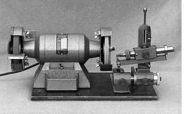
The Tinker Tool and Cutter Grinder by Guy Lautard...
This design is by the famous Guy Lautard, and he has plans and information about it on his site. His Machinist's Bedside Reader series is excellent, so I know that what he is offering is likely of extremely high quality and would be worth the price of admission. I quite like the Tinker design. It looks much simpler to build than a Quorn, and I like the idea of harnessing it to an existing grinder rather than having to fabricate a whole new grinding spindle for the machine. It seems to me that doing double duty with the grinder not only saves fabrication time, but also saves space in what will be an already over-crowded workshop for most folks.
There is also a simpler variant called a Mini-Tinker, and supposedly a design known as the Raymac may be even more capable than the Tinker.
I've added this whole topic to my Projects Wish List page.
7/28/06
A desktop 3D laser scanner for $2500. Click "Product" and then "Demo". I love that thing!
High Speed Machining at Home
Here is another neat idea from KDN Tools. These guys are attaching a Proxxon IB/E tool using a spindle clamp to get a high speed spindle for their small CNC. Here's what's cool about this. According to a thread on CNCZone, that spindle is powerful enough to cut through aluminum at 20,000 rpm with a 1/8" end mill. This is also the same high speed spindle option offered by Tormach. This would enable the HSM (Home Shop Machinist) to try out HSM (High Speed Machining) at very low cost. I'll give it a whirl once I get my mill CNC'd!
Servos on the Cheap!
Here's another tidbit. Mariss F. (Mr Gecko Himself) did a test on Kelling Technology's NEMA 34 KL34_150_90 DC Motor. Kelling is a company I've seen recommended by John Stevenson and now Mariss, two highly respected names in the CNC world. This is a 600 oz in servo motor for $109. Apparently there is some pronounced cogging, but Mariss has a report on his site about the whole test. In the end, he felt it was quite a good deal. Something for me to keep in mind when I get ready to convert my IH Mill. I know Aaron uses 600 oz in servo motors in his kits.
Leveling Screws for Squaring Mill Columns
I was reading some old posts on the IH Mill forum on CNCZone and came across some pictures of how Tormach squares their column and mill head using set screws:
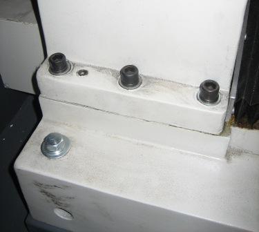
Note the set screw between the rear and middle socket head bolts that hold the column to the base...

Similar set screws on the spindle head of the Tormach...
It is interesting that the setscrews are offset diagonally on the spindle head. Presumbly there is a similar offset on the column, but we don't have a pic of the other side to tell. I wonder if the Tormach instructions detail how these set screws are used to square up the machine? Now much later, I read another post from a Tormach owner that says those are not set screws, they are dowel pins that lock the alignment in place. Hmmm. The set screw idea seemed so much better. I can't understand what the dowel pins are buying, though perhaps things are scraped in so carefully that we need only align the pins to get the mill reassembled perfectly square.
Recently, I came across someone who had done something similar to their IH Mill:
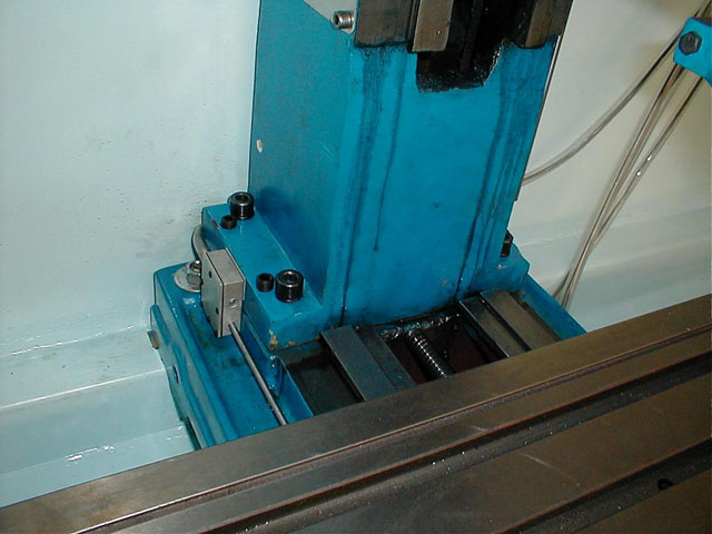
Set screws
added to an IH Mill for squaring the column...
The author of this mod to the IH Mill had the following to say:
I drilled and tapped mine for 5/8 fine set screws, works great, then find a feeler gauge to slip in next to bolt before torqueing it down and do so in stages. My collumn is within .0005 now and i figgure on checking it again after it gets shook in some. I got pics to show where i drilled. I have developed some proceedure/technique to get it righ. only back off bolt so spring washer has enough tension to hold collumn from tipping unwanted, then do tramming, if set gets too tight then back off bolt 1/8 turn or so and further adjust, lastly steal feeler of appropriate fit to jam into gap under bolt and then as you apply torque to bolt check tram and readdjust to complete. firstly tho set slides parralel to table axis as sets will get a bite into base not allowing rotation later on. if done correctly it'll be strong enough to take it all, and the feeler jammed under bolt area will aid in minimizing required readjustment as torque is applied. this is what i did. Also a not on drilling, go in steps starting with a small drill and use a drill guide for every step all the way up to tap drill size then use guide to start tap as well or it'll wander for sure.
7/21/06
A big box arrived in the mail--eBay again
It contained the scales I plan to use to make a cheezy DRO for my IH Mill. It'll be a little while before I'm ready to convert the mill to CNC (heck, it's taking forever to get done converting the lathe), so I thought it would be nice to have a simple DRO capability. I bought 3 scales on eBay for about $200. I'll need to fabricate the brackets, but heck, what else is a machine shop for? I'm about halfway through the z-axis quill DRO as we speak.
A Quick Checkup on the Health of a Milling Machine
I found this description somewhere for how to do a quick checkup on the health of a mill:
Listen for excess spindle bearing noise or clatter, throughout the speed range.Put a dial indicator on the inside of the spindle taper, rotate slowly by hand and look for run out. You would like to see less than 0.001", anywhere close to that or over means the spindle is either bent from a crash or worn or has worn bearings. If its not too bad (0.001" to 0.003" or so) it can be reground, but figure $300 to $500 plus some hassle for that.
Put a dial indicator on the table indicating against the side of the quill and in the middle of travel of the table (the most worn position) issue commands to move the table back and forth back to the same position. Do this for X,Y and Z. The difference shown on the indicator when moving from opposite directions will show you how much backlash each axis has. When this machine was new it probably had less than 0.001" backlash, it would be nice to see no more than 0.0015" or so at this point.
How much you can stand depends on how precise your planned work needs to be. My machine is at around 0.0015" on all axises and that's ok for what I do.
I'll have to try that on my IH Mill one of these days and see what the measurements are. Speaking of IH, Aaron has finally gotten his web site sorted out and all the old helpful how-tos are back up there along with some significant new how-tos on how to use the mills for production work. It's all very good information, worth a look see. One thing I noticed that I hadn't read before was a section on squaring the mill. I just got done spending quite a lot of time tramming the mill and here's another procedure that ought to be contemplated. It involves shimming the column base to make sure the z-axis is properly square. Good information!
Spring-Loaded Parallels Separator
How about this cool gizmo, a Kurt spring-loaded parallels separator:

Kurt spring-loaded parallels separators...
There is always some crazy little gizmo I haven't gotten around to buying yet! I think this particular gizmo is actually made by SPI, as Penn has it in their catalog for $39.95. It seems like the sort of thing that wouldn't be very hard to make.
7/18/06
Rotary Table Fun
I had a little fun with my new Phase II 8" Rotary Table today:
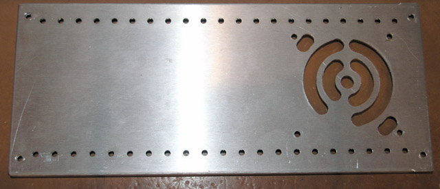
Fan cutout done with rotary table on the mill...
I just did it by eyeball and one end hung up on the handwheel so I couldn't do things as symmetrical as I would have liked, but all in all it turned out tolerably well. I think I'm going to like that table a whole lot too! At this stage I think I am within spitting distance of being ready to assemble the PC enclosure. Just a few more holes to drill, but hopefully I can get the PC up and running this weekend. That would be a satisfying step forward on the project.
Extremely Small CNC Machines
From the department of "I have no idea why, but they sure are cool," I offer a series of extremely small CNC machines:
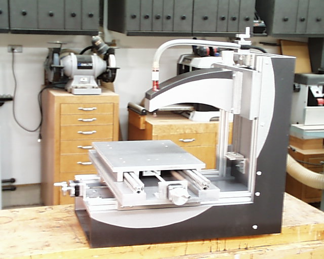
Really slick looking design. Made of MDF, 80/20 extrusions, and UHMW plastic pads so things slide. The spindle is an air powered pencil die grinder.
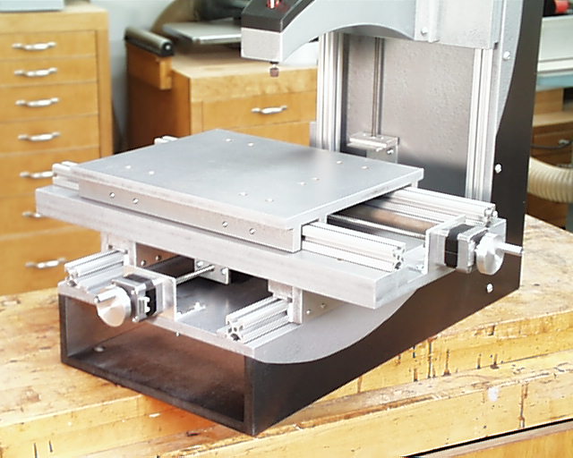
A closer view of the table. You can see the UHMW pads. Motors are NEMA 17--tiny!
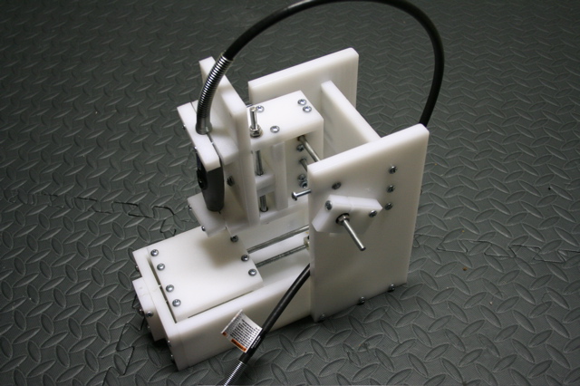
Extremely tiny--not sure what it could even be used for. Uses stepper motors salvaged from printers and a Dremel cable drive spindle...
The Fidgiting Widgitmaster's version is imaculate as always. He sure likes those T-slots!
7/17/06
CNC Lathe Conversion Status
By now, you must be wondering if I ever work on my CNC Lathe Conversion, as progress reports have been few and far between. Let me give a quick status recap, because there has been some work, albeit slow. My current task is to complete the two rack mount enclosures and build a rack to put them in. One enclosure will contain the PC, while the other will contain the DC Power Supply, Geckos, and GRex, along with miscellaneous relays and other goodies. I started with the PC enclosure, and I am just about done. There are a heck of a lot of holes to be drilled and small hardware to be located before you can turn a generic enclosure into a PC enclosure! You have to arrange for a power on momentary contact front panel switch, motherboard mounting on insulated stand offs, power supply mounting, hard disk mounting, DVD mounting, cooling fan mounting, and appropriate cutouts for all of this. I'm sure I've missed something, but I'll keep drilling holes until I've got a place for all the components and then I will connect them all up and try to bring the PC up. Once it is running Windows XP happily, I will move on to building the second enclosure, followed by the rack that will hold both enclosures, a keyboard tray, and a stalk for my ELO touch panel screen. Whew!
Along the way I have also managed to order a variety of components that will be needed, including:
- Shielded cable from Action Electronics for the Step Motor (and potentially encoder) wiring. I went ahead and bought a full spool as I may want to use it on a variety of projects over time.
- Connectors. I decided on 6-pin microphone connectors, also from Action Electronics.
- A lot of other miscellaneous odds and ends like a SPST switch with safety cover (see below) that will be used to control power to the driver electronics enclosure.
I am hoping that with the enclosures made, progress can pick up. Since the work of building these enclosures is relatively boring, I keep taking breaks to go do "real" machining, such as the vise stop I recently made.
Odds & Ends
7204CTDULP4 Universal Duplex pair of 15 degree angular contact bearings suitable for mounting ballscrews or perhaps spindles. These are ABEC-7's for $199.95 from the reliable firm of Nachi. Not bad! Got the tip from a guy on HSM. If I could find a set with a larger angle and designed for heavy preload (these are for "light"), they would be even better, but these are pretty nice for the price. If you don't want to spring for the ABEC-7's, you can get some really cheap "B" angle 7204's for only $23.88 in ABEC-3. These latter are probably also not too bad for the HSM project.
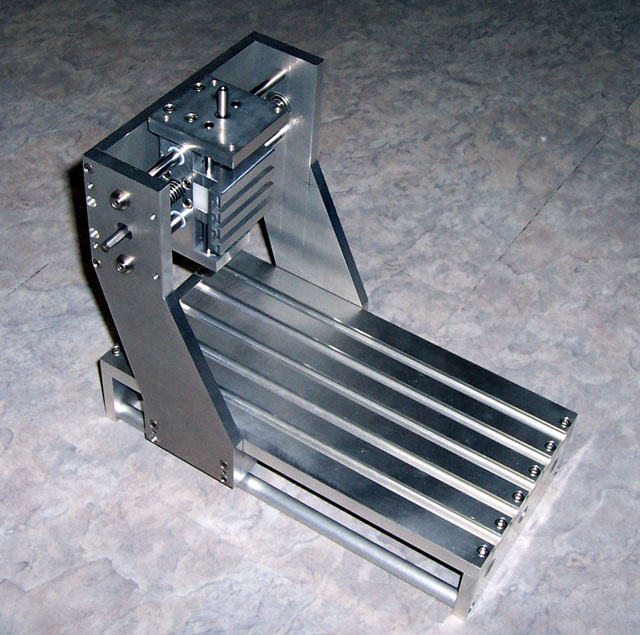
Z-Axis for a Router
How about this for a nice little Z-axis for the router crowd:
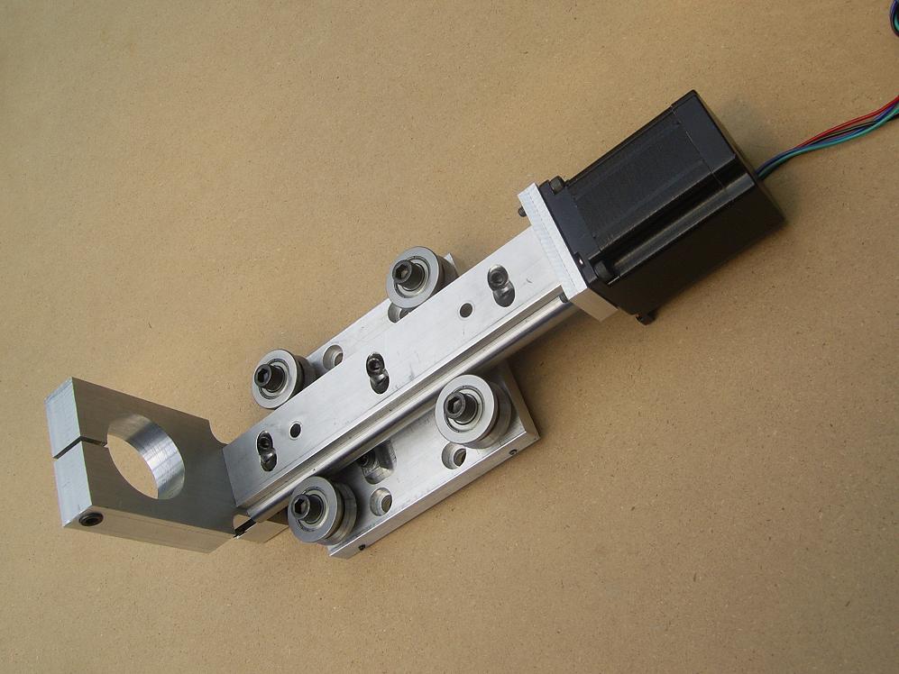
Interesting slide design, the round rails are embedded in the aluminum and held with bolts...
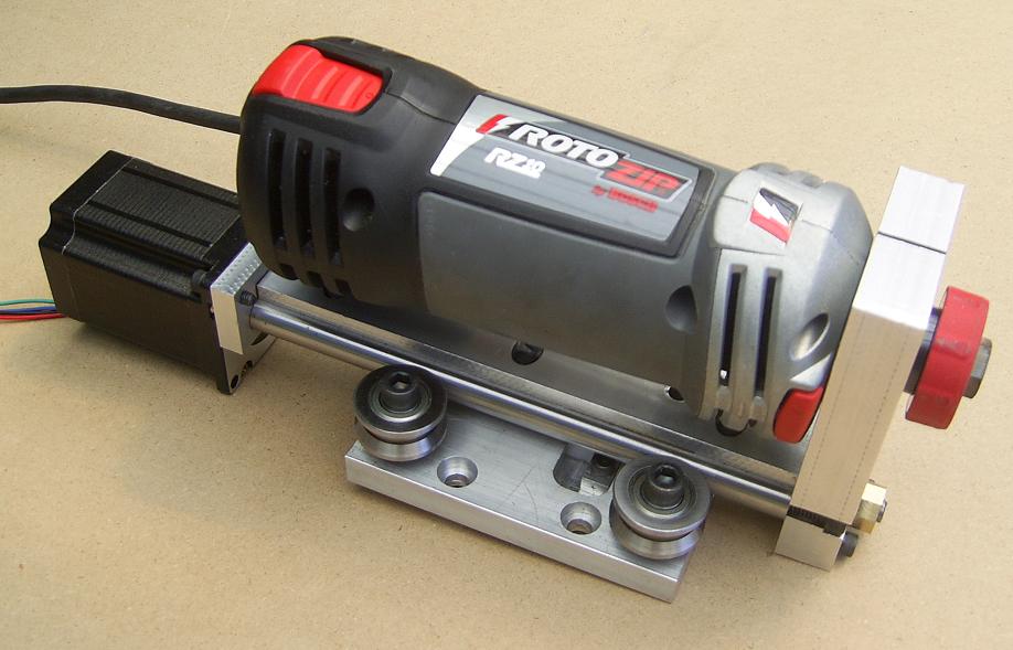
Uses a RotoZip router...
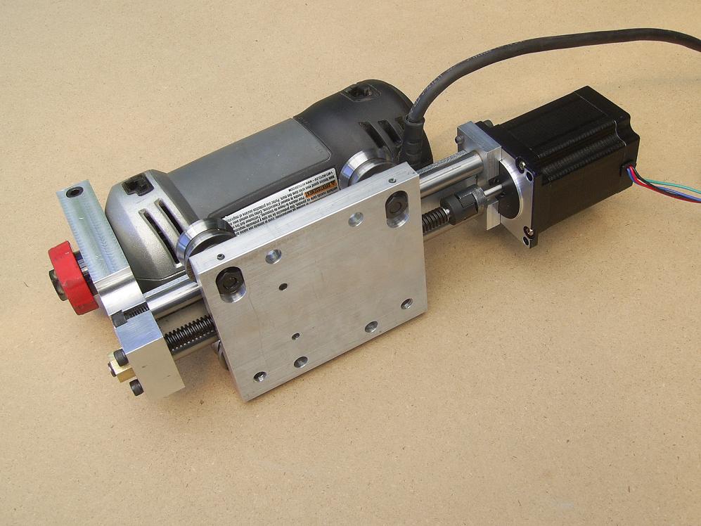
This fellow (eBay seller yukonjasper) is selling these on eBay for $175 buy it now, without the Roto-Zip or stepper motor. Seems like a pretty nice deal.
Yuasa R8 Quick Change System
I came across this nifty set of Yuasa Quick Change toolholders for R8 machines (like Bridgeports and my Industrial Hobbies mill):
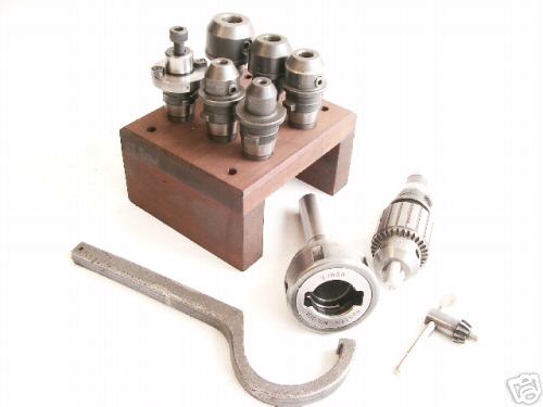
The Yuasa Quick Change Set...
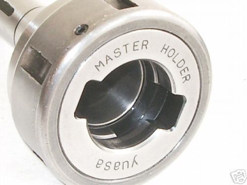
Quick Change R8 Chuck...
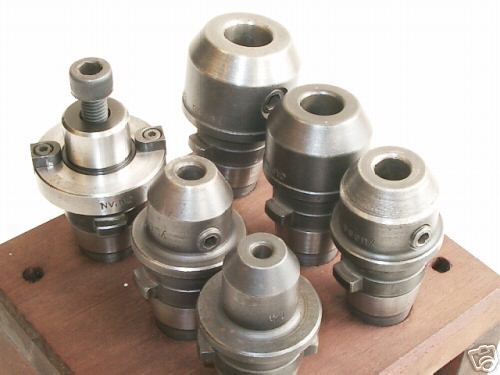
A set of the holders...

Aren't they Kewl?
I'm not sure how the holders get locked into the chuck, but they sure are cool. The seller didn't know much about them, but thought they might have the brand name "Kwik Switch". This set sold for about $320, and I kick myself for not stepping up to take them. Oh well. I did purchase plans to make a powered drawbar for my mill from a butterfly impact wrench. That would also speed tool changes up considerably.
Tip of the Day: If you are getting long stringy chips, crank up the speed.
7/16/06
A New Asian CNC Mini-Lathe
I love the travelling chip guard on this CNC Mini Lathe:
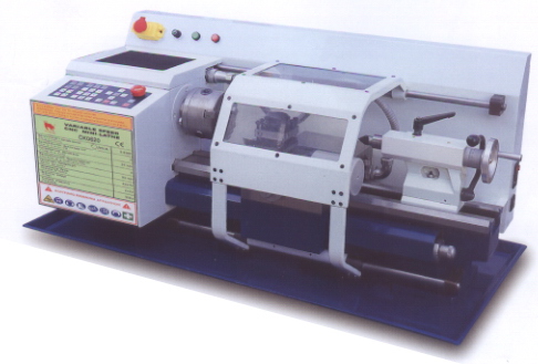
Nice travelling chip guard!
I'm thinking of making something similar for my lathe at some point. I think what I will do is get some sheet Lexan and bend it over a cylindrical form using a heat gun to soften it up. I might even make one up the full travel of my lathe so I don't have to fool around making a rail system so it moves.
JerryFlyGuy's Flat Rail Installation for a Gantry Machine
Many moons ago (4/9/2006, to be precise), a fellow named "JerryFlyGuy" set out to determine how best to install a set of linear ways in as true, flat, and square a fashion as possible. Many possibilities for it were discussed in quite a long thread over at the CNCZone. At last JerryFlyGuy settled on an approach, and a very interesting one it is too. He is using a very fine wire as a continuity test to tell when the rail is straight and a little jig (laser cut) that fits over the square tubing with screws that let him tweak the rail left or right:
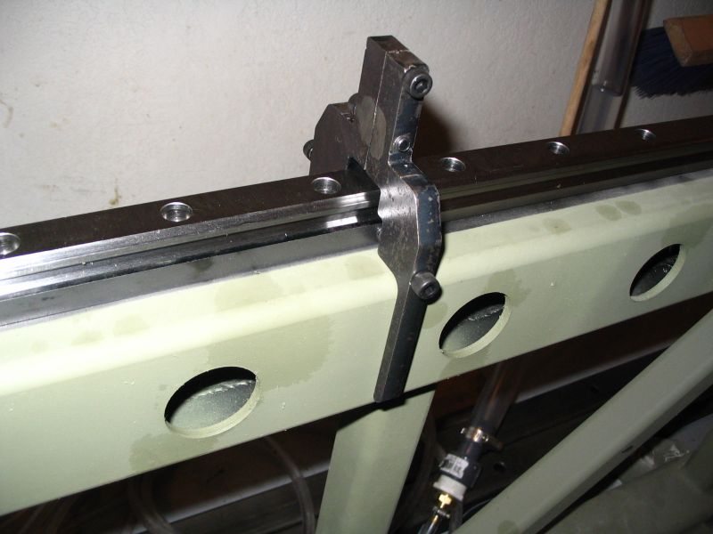
Straightening jig used to position the linear rail onto the square tubing...
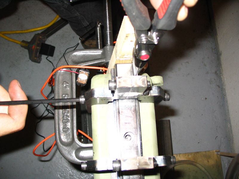
Pliers are holding the continuity test wire while the allen head is used to tweak the rail left or right. Once it is in the correct position, Jerry then drills a mounting hole. He has started off with drill bushings to create pilot holes.
I believe once Jerry gets all of the holes drilled his next step will be to pour a Turcite like substance between "dams" to provide a flat surface to mount the linear ways on. More news as it develops.
7/9/06
Motor Electronics Safety Switch
: I want to put a safety switch on my CNC Lathe motor electronics. I plan to wait on firing them up until the PC is booted and Mach 3 is up. I suspect it can also serve as an addition E-Stop. I'll wire the incoming power to everything in the box through this switch:
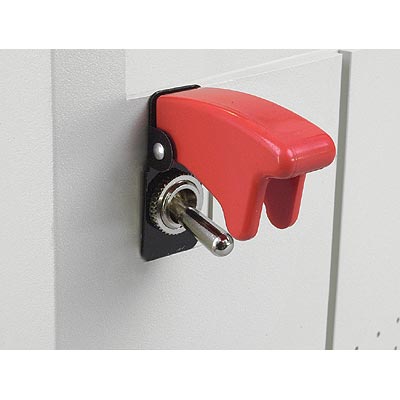
Safety Switch for Motor Electronics Enclosure...
Action Electronics sells them too if you search on "Safety Switch".
7/8/06
Roh'lix?
An interesting alternative to the ballscrew for CNC applications is called the "Roh'lix". They have virtually no backlash, and are much less susceptible to contamination than ballscrews. They have the ability to slip if overloaded, and I suspect this potential limits their thrust and may make them susceptible to losing steps in open loop systems. The Roh'lix runs on just a steel shaft, which are certainly available pretty cheaply. May be worth a look for certain applications. Given their low thrust capability, they are said to be excellent for CMM machines. I wonder how well they would work for a plasma table? They are also available with a quick disconnect option which would make manual positioning possible. The Roh'lix patent is 4947698. I wonder how hard it is to make them?
A similar idea is the "rolling ring" drive, which definitely looks buildable.
Making Connecting Rods for a Model Engine
I thought this was a very cool picture that explains a clever way to make connecting rods for the Model Engineer:
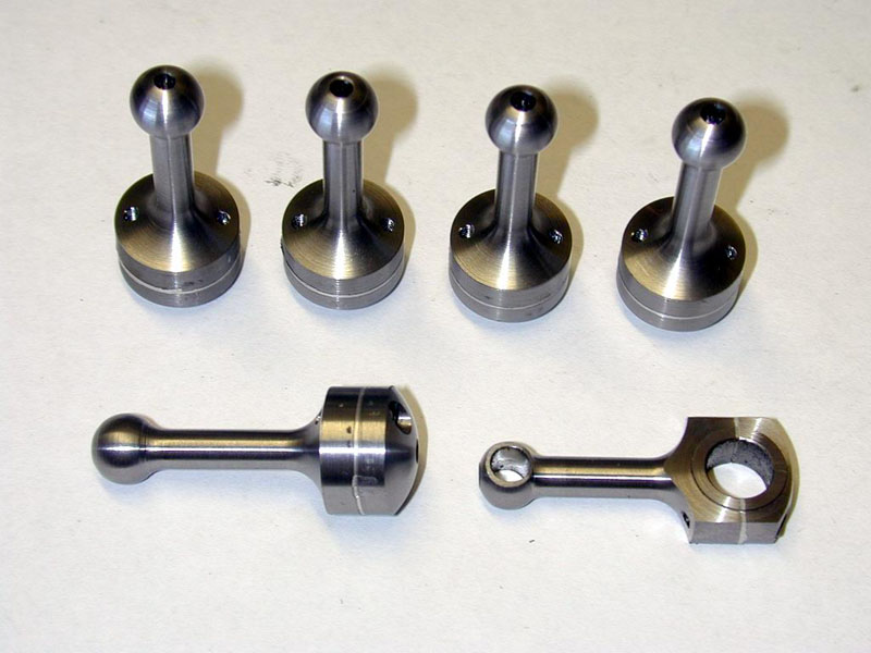
First turn them on the lathe, then finish with a mill. Note how the split portion already existed on the turned pistons. These are for a scale model of the DeHavilland Cirrus aircraft engine...
7/7/06
I Want a Centering Scope!
I really want a centering scope--I just think it would make it so much easier to line up precisely in the mill or even to use a 4-jaw chuck. They are expensive. I have missed out on them on eBay probably 6 or 8 times by just not being willing to bid enough. They usually go for about $120 or more. It occurs to me that it's a bit silly this function is not handled by a webcam-like approach, and then I got to looking at the Intel digital microscopes (QX3 and QX5). Well it seems there is a great piece of shareware called miXscope that really enhances these beauties and this just might be the ticket to use one as a centering scope. There's just the issue of mounting it accurately to make it work as such. I may look into this, or I may just deal with what a real scope costs.
Centering Scope Used to Precisely Position On Center of Part...
7/03/06
"Printing" 3D Objects in Steel
Just came across one of the coolest things I have seen in a long time. How about the ability to "print" 3D objects in steel:

Some 3D printed art by artist Bathsheba Grossman...
It's almost like the materializers in Star Trek! Artist Grossman starts from a Rhino 3D model and the machine can directly reproduce that model from metal powder in steel or bronze. Apparently its a laser lithography technique where the laser interacts with fine metal powder that is coated with a laser-sensitive binder. That binder solidifies the object layer by layer. Once it has been fully solidified, the object is placed in an oven that has just the right temperature to weld the metal into finished product with reducing it to a melted puddle. Very cool!
Bathesda also provides a fascinating sculpture called "Little Star" that she's put into the public domain so others can build them:

Little star is intended to be plasma cut from metal and then assembled with silver solder or welds. The plans she provides are for a 14" tall model, but I would love to make one much larger. Will have to look at what my plasma table is capable of when I get it built.
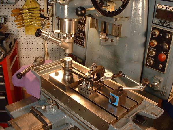
Cross Drilling Jig
Came across the idea of a cross drilling jig over on Practical Machinist:
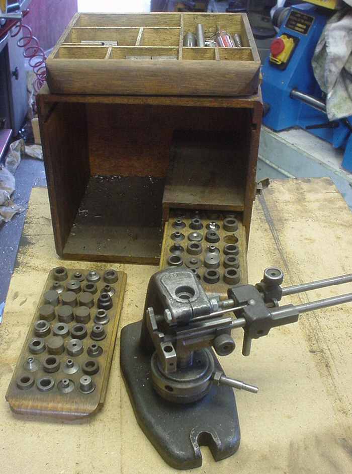
These are handy when cross drilling shafts. You'll note it is build around a captive V-Block, and there is a gizmo to hold a drill bushing at the top that is on a couple of sliding rods. This one is store bought, but it seems like an ideal quick project for a machinist to build one.
|
Do you want to be a better CNC'er in 37 Seconds? Get Better Tool Life, Surface Finish, and Material Removal Rates Fast. It's that easy. You can install and get results now.

|
||||||||||||||||||
| ||||||||||||||||||