|
|
|
|
|
|
|
Do you want to be a better CNC'er in 37 Seconds? Get Better Tool Life, Surface Finish, and Material Removal Rates Fast. It's that easy. You can install and get results now. |
August 2009 Through October 2009 CNC Blog Archive
10/31/09
No Trick, Here's a Treat: Bandsaw Vise Trick
Saw this on PM from Ray Behner:
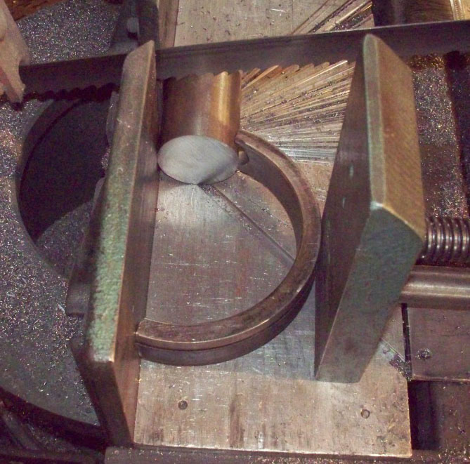
Clever!
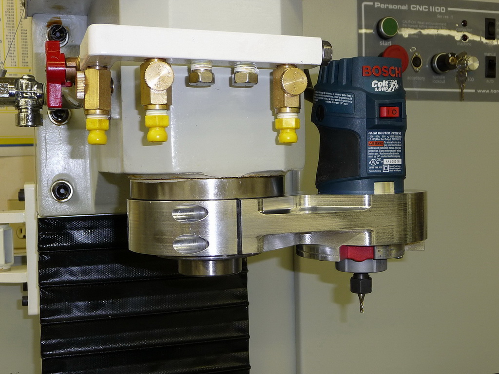
New High Speed Spindle Ideas
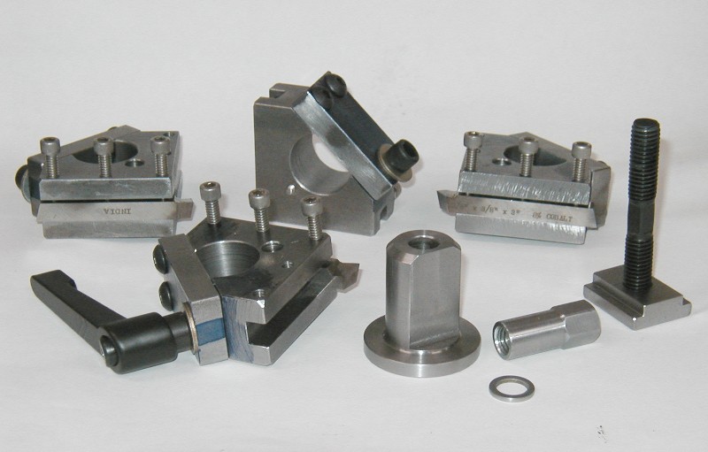
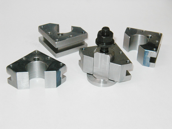
I've got a page where I am collecting ideas for attaching high speed spindles of one kind or another temporarily to my mill. I added some new pictures to the page today. I call such pages "Idea Notebooks" and there is a list of them on the Cookbook Page. Here are the piccies I added:
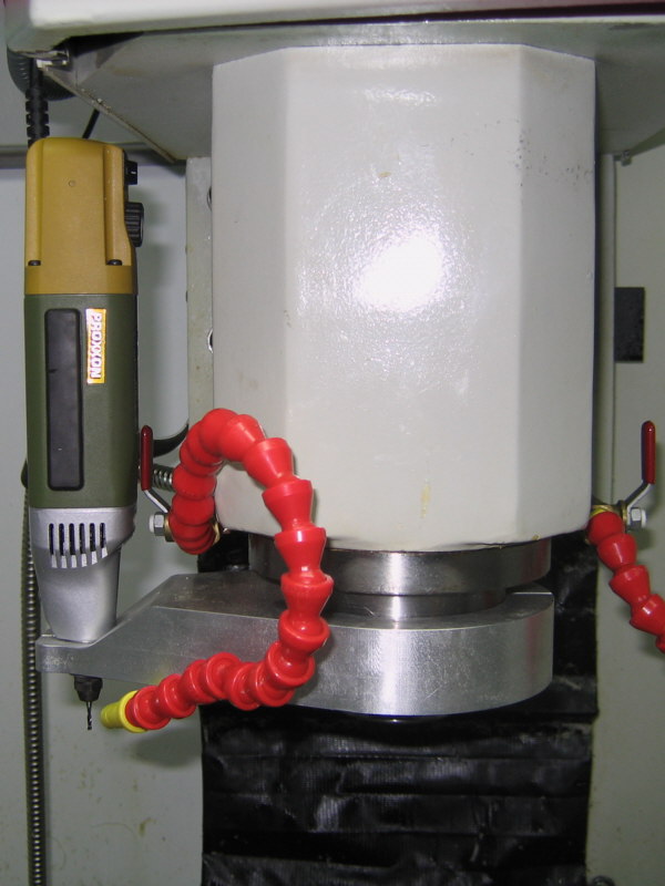
Coolant Collar Idea Notebook
Speaking of Idea Notebooks, I've added a new one to track ideas for Coolant Collars:
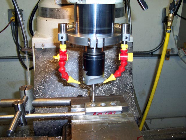
The Widgitmaster's Coolant Collar...
10/16/09
Sturz Milling and Other High Tech Milling Tricks
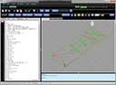
I wanted to add the calculations for ballnose cutter compensation to my G-Wizard Feeds and Speeds Calculator, so I got to researching ballnose cutter compensation calculations, scallop height calculations, and all that sort of thing. Somewhere along that way, I came across references to "Sturz Milling." This Ingersoll treatise on their indexable ballnose cutters had some of the best data.
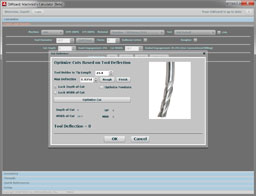
The notion here is that the speed of a ballnose cutter varies depending on your depth of cut. If you have very little depth of cut relative to the diameter of the ball, you actually have a much different effective tool diameter. You'll need to speed up your rpm's to take into account that effective diameter. For example, an 0.100" depth of cut on a 1/2" ballnose endmill actually uses an 0.400" effective tool diameter, not the 1/2" you may have thought. G-Wizard figures out all of that stuff for you just by checking a box.
But what is this "Sturz Milling?" Essentially, it is the idea of tilting the cutter relative to the normal to the surface being machined to keep the very tip from cutting. That tip is a "dead spot" on the cutter because it isn't moving very fast. Being able to easily do these tilts is a big advantage for a 5-axis machine doing 3D profiling. However, even on a 3D mill, you can try to orient the workpiece so the cutter is never perpendicular to the surface you need to 3D profile. For some parts, this may make a big difference both in terms of how fast you can machine and for the surface finish.
The Ingersoll pamphlet has a few other interesting ideas. For example, the suggest reduce the feedrate as an indexable cutter enters the cut. The reason is that until you reach full engagement, not all the inserts are cutting. There is definitely a noticeable roughness I've seen at the beginning and end of a pass with the facemill, for example. It would be interesting to fool with the feedrates there to see if it could be smoothed out a bit.
They also suggest slowing down in a corner by 50%, but not dwelling. Corners are definitely an area where there can be a lot higher engagement, so slowing down there can be helpful. Conversely, if you have created a g-code program that works great through the corners, you're probably going too slow on the straight paths!
Another great Ingersoll resource is this tech pamphlet on milling cutters. It's got all sorts of great information on chip thinning, lead angles, and other useful data. For example, they discuss the impact of lead angle on milling cutters. Consider two face mills. One has a 90 design and can be used to create square shoulders. The other has a 45 degree design. Why would you ever want the 45 degree face mill? Because the lead angle changes the performance of the cutter in some interesting ways. Consider the geometry:
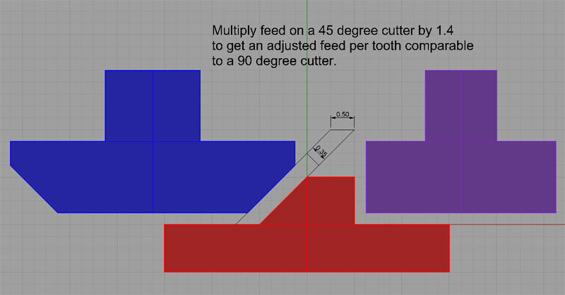
The 45 degree face mill is on the left, and the 90 degree is on the right. You can see from the diagram that because of the angle, the equivalent depth of cut is much less for the 45 degree mill. In fact, you have to multiply the feed by 1.4 to get the same depth of cut, which corresponds to the chip load. So you can feed a 45 degree face mill 1.4x as fast as a 90 degree face mill. Whoa! It turns out your surface finish with the 45 degree face mill is often a lot nicer as well.
As you can imagine, similar calculations can be done for face mills that have circular inserts. These are often called "button cutters" although some manufacturers call them "toroidal cutters" too.
Have you heard of "high feed" inserts or cutters? I like to think of them as combining some of the best of both lead angle and button cutter capabilities. Imagine an insert that has radiused corners with a big radius (that's the button cutter) and further, imagine the insert is mounted at an angle so that that straight edges connecting those corners generate a nice lead angle effect too.
Cool beans!
10/12/09
Star Trek in the Machine Shop: Tricorder or Phaser?
Yes, I'll admit, I'm a Trekkie. That's getting to date me I think. What's this all about?
Check out these devices:

The sorter performs a function not unlike Mr Spock's Tricorder (although it looks to me more like a Phaser!). Specifically, you point it at a piece of metal alloy, pull the trigger, and it tells you what the alloy is. How does it work? It's an X-ray spectrometer. It basically zaps the metal with an X-ray and then looks to see what the metal does in response.
Cool beans!
Manufacturers use them to make sure alloys on projects where the material has to be "right" are as specified. It's all part of a manufacturing process called PMI for "Positive Material Identification."
10/11/09
Servo Drive Reviews and a Big Drive for Your Spindle
Macona on the HSM board recently called my attention to this review page for servo drives done by TheCubeStudio. That's a very cool review page, nice to see all the pros and cons from someone that actually tried to get all of the drives working. I learned about a couple of drives I would not want to try my own money on!
Because of the reviews, I became aware of the reviewer's favorite drives which are made by www.cncdrive.com out of Hungary. They look like extremely nice drives. I am always on the lookout for larger drives, on the off-chance I want to use one for the spindle of a CNC. Big drives are often expensive and not available to the low end market unless via the surplus and used markets such as eBay. It's very handy to have a servo driving your spindle for such things as positioning for a tool changer (CAT40 and many other tapers have "drive ears" that have to be lined up), or in the case of a lathe, indexing for live tooling, for example to drill a bolt circle on a flange.
CNCDrive's largest drive is called the Dugong, and it can handle 160V at 35 amps. With a 20% safety factor, that would be about 4.5 KW = 6 HP. That's more than enough for a lot of spindle purposes. They cost less than $200, which seems very reasonable. The other thing I like about these drives is they connect via USB to allow tuning with software, so no need for an oscilloscope.
I may have to try one at some point!
The other cool device from Macona's post is the Teensy Arduino USB controller. These little boards are a complete PC on a chip with the ability to control signals such as relays and so forth. Lots of possibilities for such an easy-to-program and inexpensive device. The thread talks about using steppers or servos to automate a surface grinder that lacked a power feed, and that would be an excellent place to start.
10/3/09
Chuck-In-A-Vise and Other Wisdom of the Widgitmaster
I liked the Fidgeting Widgitmaster's little fixture to keep a small 3-jaw chuck handy in your Kurt vise:
I guess you can leave the key in the lathe chuck when it's on the mill!
The chuck is mounted on a steel block so it's easy to clamp or just drop into the vise. It'd be easy to use on a drill press or rotary table too I bet! It would even be handy just for the bench.
I need to make one up for my own shop.
9/20/09
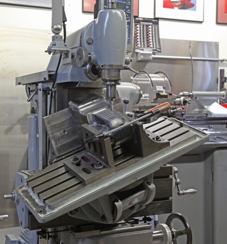
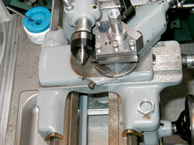
Milling Quite a Compound Angle
Some machines have interesting capabilities:
9/13/09
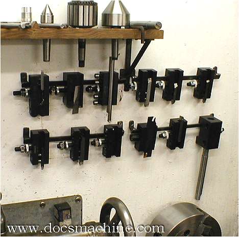
Organize Your Lathe Tooling: New Idea Notebook
I came across a bunch of new ideas for how to organize your lathe tooling, so I created a page to show it off. Idea Notebooks are what I call pages that have lots of ideas for how to do a particular project. You can see the list of them on the Cookbook page.
Here is a typical sample from the Lathe Tooling Organization page:
9/12/09
Widget Squares a Block (And Builds a Cool CNC Router)
I just got done looking through the thread on one of the Widgitmaster's latest creations on CNCZone. He's busy converting one of his earlier 24x24" routers from v-groove pulleys to round linear rails. Keep an eye on it if you like the machine that results as he will be selling it on eBay.
I always learn a thing or two watching Eric's meticulously documented projects, and I like to share those learnings here.
Here are some highlights:
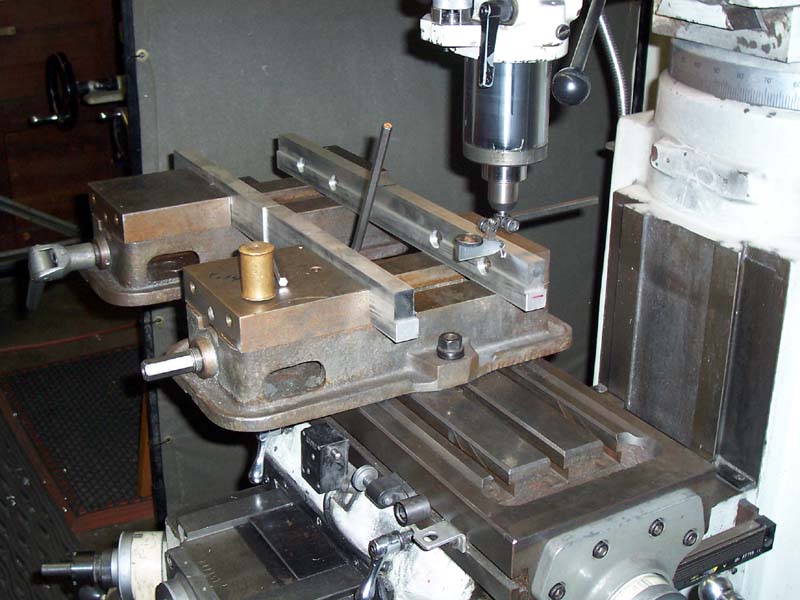
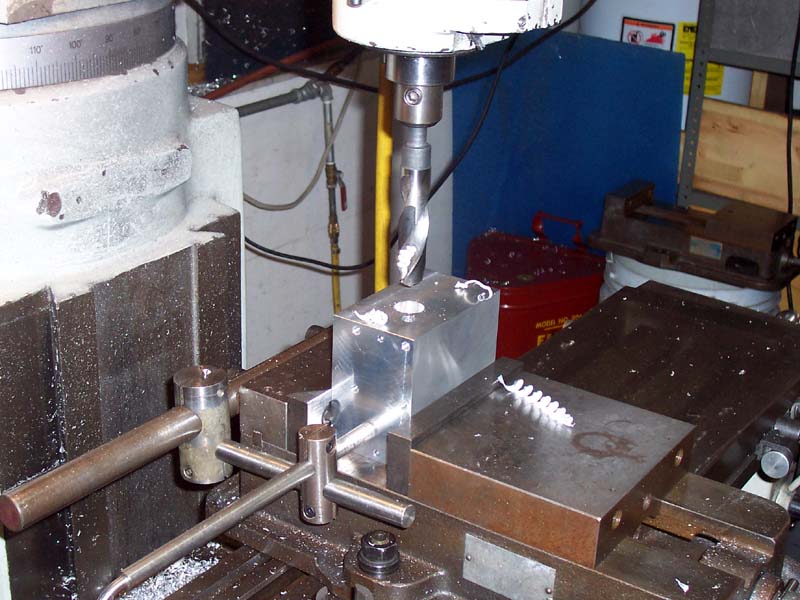
Got a big workpiece? Make yourself a rig like this. Aluminum softjaws span 2 vises. Widget is tramming the vises with his DTI against the jaw...
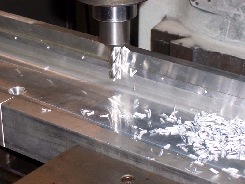
Yes, it's aluminum, and yes that's a 4 flute endmill. Why? Because it isn't a pocket, it's peripheral, so the chips can easily get out of the way. And, because you can feed a 4 flute twice as fast for a given spindle speed. Nicer surface finish too, in my experience...
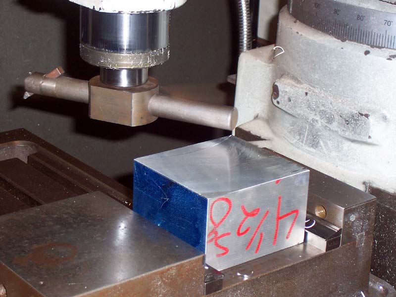
Two things to note while squaring this block. First, check out the Starrett vise hold downs on either side of the block in the vise. Need to get a set of those myself! Second, check out the great big fly cutter he is using...
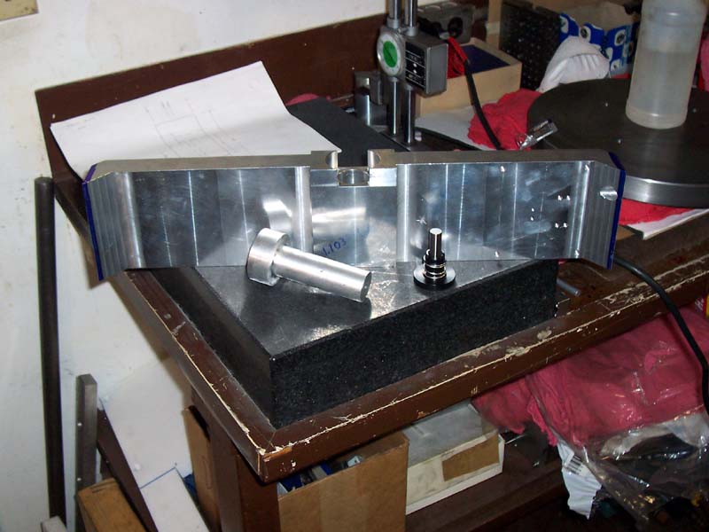
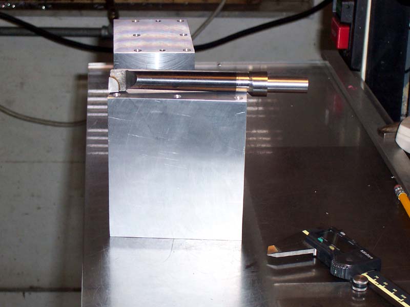
Having changed leadscrews, Widget needs to rebuild the hold to fit the new leadscrew. To do that, he wants to shrink fit that plug into the hole and then machine the plug for the new mounting...
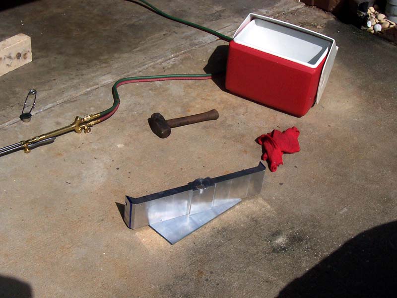
The plug, 0.0005" oversized, goes into the ice box, and the assembly is heated with the OxyAcetylene torch. Drop the plug in and tap it with the sledge and it is going nowhere!
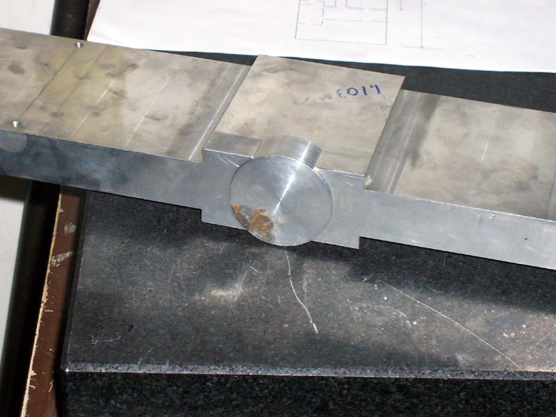
It might as well all be one piece of aluminum...
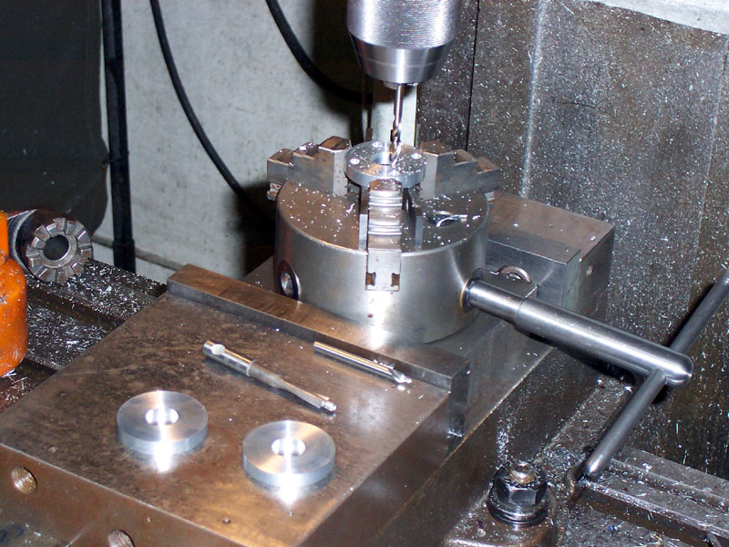
Do you have a problem with larger twist drills twisting in your chucks and getting scarred up? I do. Silver and Demings are the biggest, but they all share a common shank size, so you can stick them into an endmill holder. A little Weldon shank action on that big bit and you'd really be able to lock it in place in the holder...
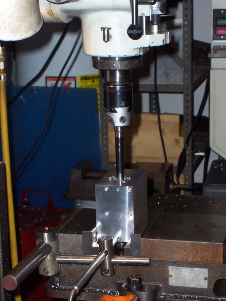
Boring a really deep hole, how do you minize the chatter?
Take a large diameter lathe boring bar, one with a shank that would never fit your boring head. Turn down the shank until it does fit the head, like a Silver and Deming twist drill bit. Smart!
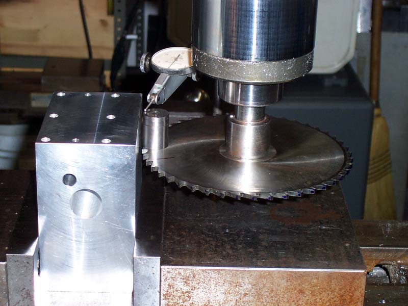
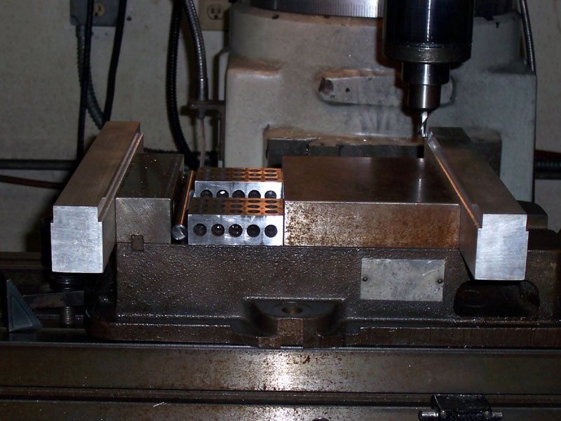
Indicating the slitting saw in with some space blocks so the middle of the saw cut is just where it needs to be relative to the top of workpiece. Widget suggests plunging the saw straight in rather than starting from the side when cutting because the hole will keep the saw centered instead of pulling it off axis...
Lots of goodness here: Outside vise jaws will be used to clamp a big workpiece. Not only are the outside, but they are wider than the vise. Widget is milling a step into them to use instead of parallels (how will you get parallels in there anyway), and since the steps are milled, they're prefectly trammed. Lastly, check the 1-2-3 blocks and drill rod. Drill rod keeps from overconstraining the setup (i.e. makes it more accurate) and having them in there loads the vise as though there is a workpiece in there...
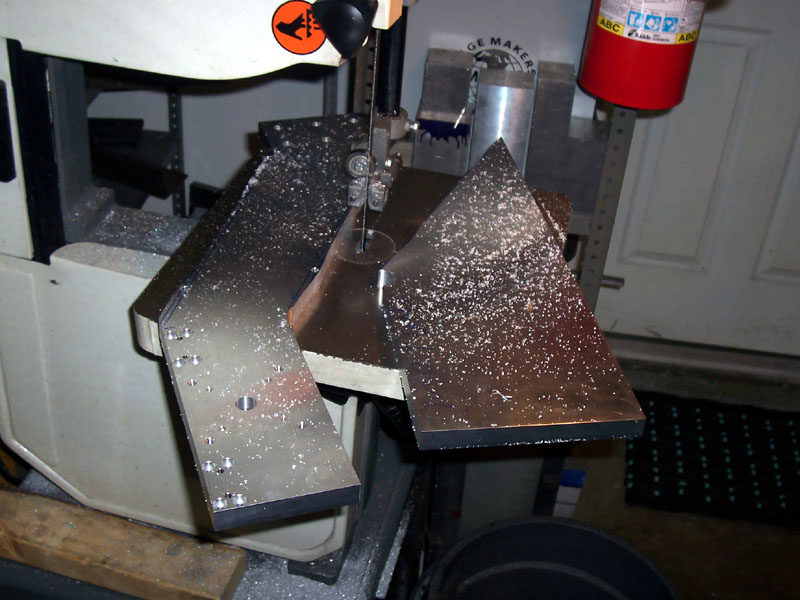
This gantry router uses 2 vertical arms. Widget rough saws the arms on the bandsaw, but all edges will need to be milled square...
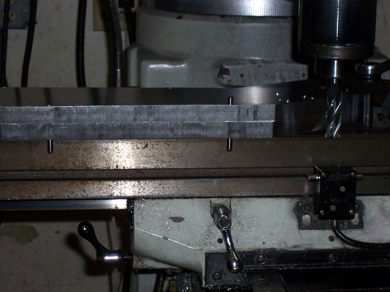
Widget had been thinking ahead. He has two holes for dowel pins that in the material that will be milled away. The dowel pins let him line up the milling pass perfectly because they align the workpieces against the square mill table edge...
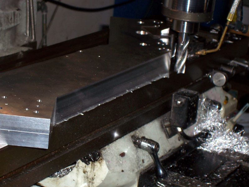
Having clamped the workpiece using the dowel pins for alignment, Widget removed the pins and made his milling pass. Now he has a nice square edge in exactly the right place!
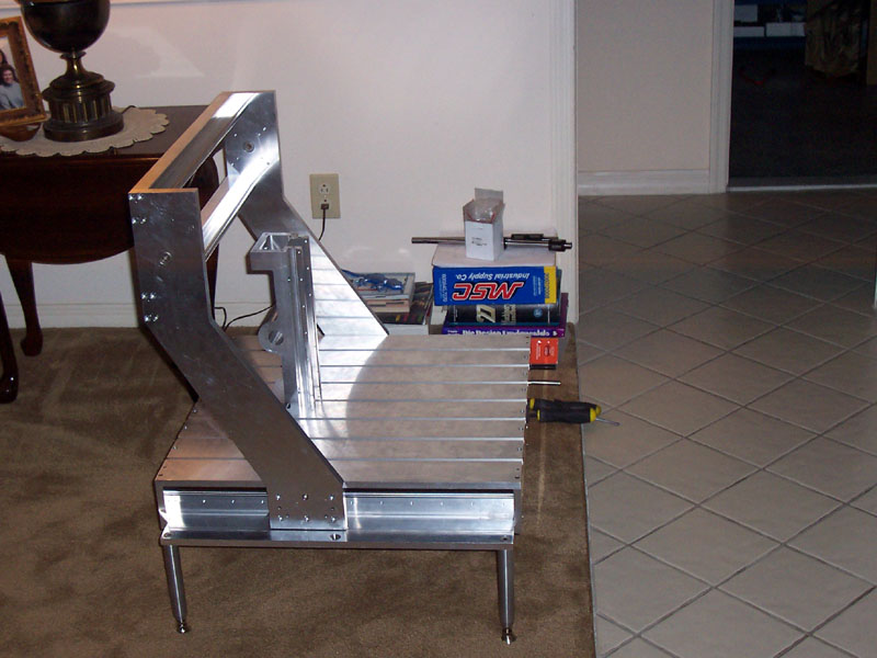
Here's What We're Building. Looking Good!
9/5/09
Check Out Glacern
I just got some real nice ER32 collet chucks on R8 shank from Glacern. Cool products and good people to work with. I love the idea that of companies like Glacern and MariTool building tooling domestically and selling very nice tooling at competitive prices. Check out this great video Glacern did:
Very cool: Gotta love that killer Mori VMC too!
Their vises look very nice as well. Would be very tempting if I were in the market for one.
8/30/09
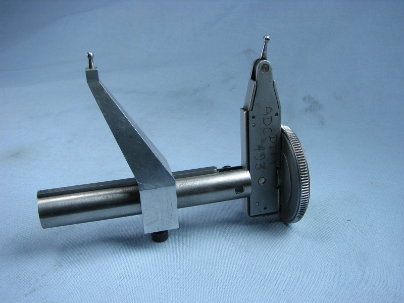
Clever Shopmade Bore Measuring Tools
Nice thread on HMEM about these:
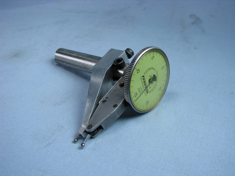
The fixed jaw slides along the shaft. The movable jaw is the indicator's probe...
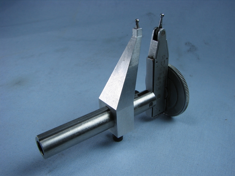
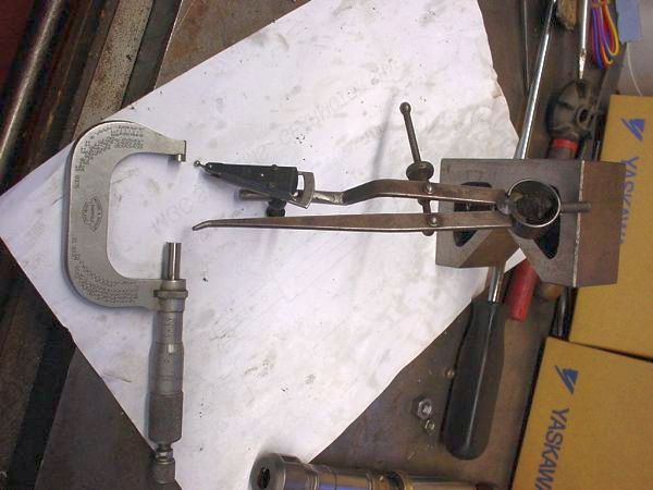
And another from the same thread by John Stevenson:
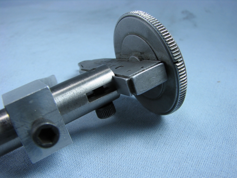
Finally, this beauty is evidently a design published in Model Engineer magazine in the 1980s:
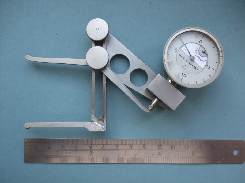
Set to maximum bore diameter range...
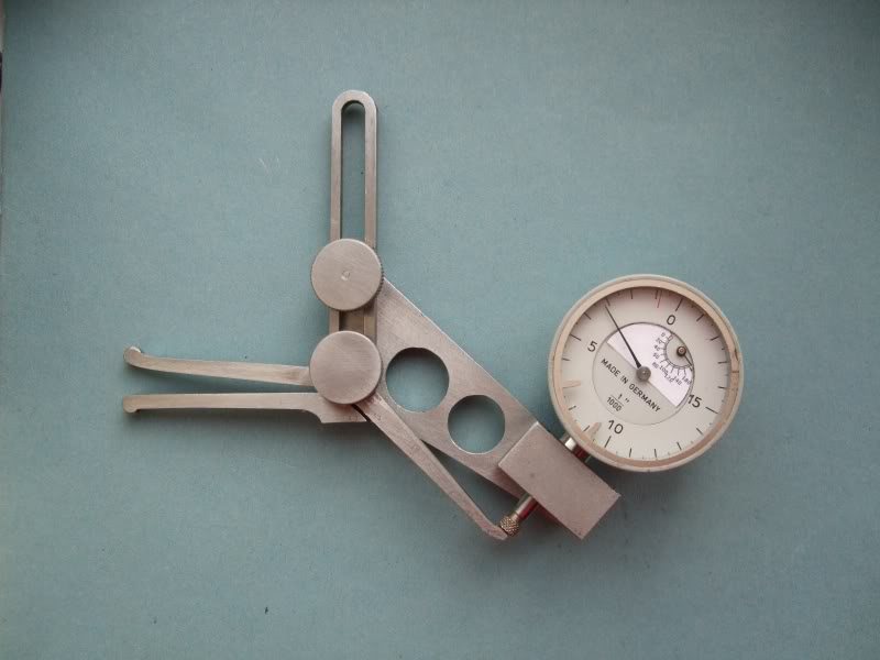
Set to minimum diameter range...
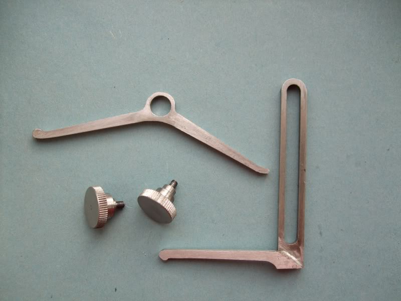
These are all relative measuring devices. They need calibration against some standard, though a micrometer should work easily enough. They can then tell you how the bore compares to the standard using the dial indicators.
8/24/09
Offset Relative to the Machine, Not the Part
I was reading a thread on Practical Machinist this evening that jogged some thoughts loose that had been rattling around, but which I had not gotten into a coherent state:
On a CNC machine, you want to set things up as much as possible so everything is relative to your machine, not your part.
I can tell you from experience that this isn't how newcomers think about it, but it makes a lot of sense if you're trying to do anything on a production basis versus a one off. Most of the time I've been coming in and touching off some feature of the block I start from, for example touching off the top of the part to establish the Z = 0.0 datum. Typically, I would slap a chunk of material in the vise, touch off by eye (close enough) to start squaring the piece, get it squared, and then wind up touching off again with a Z-axis presetter before I started my CNC job.
If you're setting up relative to a part, you've got to indicate the machine, touch off, or otherwise let the machine know where the part is for each and every part. But if you're set up relative to the machine, that's not a problem because your machine isn't going to move around--or at least it had better not!
My friend Pete in Hawaii takes this one step further. He has established a reference 0, 0, 0 point relative to the vise jaws in his mill. He does all of his CAD/CAM work with the expectation of that reference point. This way, he drops a block into the vise, hits the green button, and away it goes. Multiple vises? You've got offsets to deal with that too. Likewise if you run a fixture plate, it would seem advantageous to get out your probe and log the coordinates of all the salient features of the fixture plate. For fixtures, a lot of shops put a feature on the feature that they can dial in on once the fixture is installed on their mill. I've even seen this done on soft jaws for vises, which are not repeatable when you swap them on a Kurt vise. A precision hole is one easy feature to dial in on for vise jaws.
What about dealing with variations in rough workpieces? Set some standards. Machine Shop Trade Secrets suggests you bandsaw workpieces to within a 1/10 of an inch. If you're running production, that's probably not a bad figure to adhere to. Use a stop on your saw if you're manually feeding to make sure each piece comes out close enough. A variation of 1/10 of an inch is nothing to a face mill if you're going to surface that edge before starting to machine. If you're on a smaller machine where it really matters, set it up to take 1/2 of that 1/10th out (50 thousandths) on the first surfacing pass. If you're really accurate to 1/10, you'll be pretty close to that 50 thou cut or it'll be less. If your parts are 2D contoured with a laser or water jet before they go on the CNC, they should be well within these tolerances.
8/16/09
I've Been Busy!
I've gotten a number of notes lately from folks wondering what I've been up to and why it has been so long since I've posted an update to the Cookbook. The short answer is I've been busy on other things--it's probably been a month since I did anything in my shop. To give a little more color on that, I've been busy with a combination of vacation and accepting a new job as CEO of Helpstream. Needless to say I am still not caught up on the latter--CEO Is a big job. But, I am starting to glimpse a slight glow ahead. Hopefully that turns into light at the end of the tunnel in the not too distant future.
Meanwhile, I do still find a little time to read online so I'll try to do a little writing. In between reading about machine work, I have also been doing a little programming that's related. I'm going to keep that one under wraps for the time being, but eventually it will turn into a nice surprise I think.
A Poor Man's QCTP Dovetails
Interesting thread over on HSM about ways to make dovetail holders for your lathe QCTP if you don't have a dovetail cutter. BTW, it's not hard to make your own dovetail cutter as I did some time ago.
Most of the thinking on the thread has to do with making the dovetail in several parts ala this drawing by Brian Rupnow:
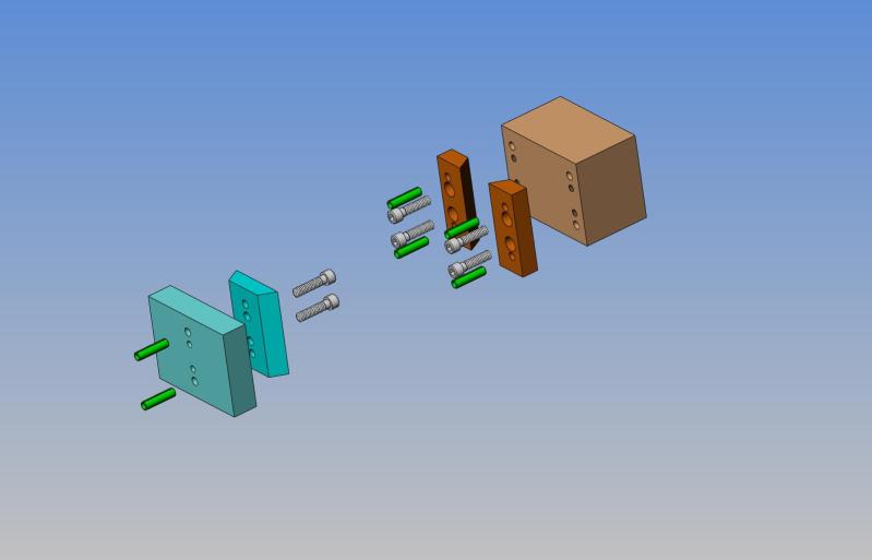
Note the use of dowel pins to accurately locate the femail dovetails. Another approach might be to machine a shoulder they could position against. Some locating is needed because bolts are not for locating unless they have shoulders so they can act like the dowel pins.
Atty showed a picture of a QCTP holder made the way Brian suggests and sure enough it came out pretty nicely:
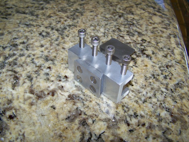
No dowel pins, but he says it works well. For holders, especially, I think a machined slot could provide the locating as well as a little more rigidity.
Lastly, Paul Alciatore presented this very slick alternative to the dovetail approach:
This design would be extremely easy to make. It clamps against the flat of the toolpost. I assume height could be adjusted with a setscrew bearing against the holder flange at the bottom. Generally, it looks more solid to my eye than the Aloris-style.
|
Do you want to be a better CNC'er in 37 Seconds? Get Better Tool Life, Surface Finish, and Material Removal Rates Fast. It's that easy. You can install and get results now.

|
||||||||||||||||||
| ||||||||||||||||||